Introduction to Embedded Systems
Arduino Uno Microcontroller Board
This course is about programming embedded systems. Embedded systems are often controlled by microcontrollers. A popular platform, especially for educational purposes, is Arduino. Many different Arduino boards exist. Among those, the Arduino Uno (USD $27.60 at the time of writing) is one of the most basic and also one of the most popular to get started with electronics and programming of embedded systems.
Using Real Hardware or Simulation?
This course was developed for use with the Arduino Uno microcontroller board, which you can connect to your computer via a USB cable, and real electronic components. However, alternatively and quite equivalently, you may choose – at your own discretion and initiative – to use one of several publicly available online Arduino Uno simulators, which simply run in your web browser. They simulate the functionality of the Arduino Uno just like a real one and allow you to create associated electronic circuit diagrams directly in your web browser window, thus eliminating the need to purchase any hardware for this course. In one of our upcoming lessons, we will explain to you, how to use such simulators, because it is an important skill to have for prototyping in any case.
The beginnings can be sometimes daunting, so please feel free to contact us, if you have any questions regarding both hardware purchases or simulation. We will be happy to advise you.
Arduino Hardware
Whether you choose to use real hardware or decide just to simulate it, you need to learn about the hardware. Learning about the physical Arduino Uno is what we are going to do for the rest of this lesson. In the next lesson, we will learn about the freely available Arduino IDE software for your computer, which will allow you to write computer programs for the Arduino and to upload them onto the device.
The image below contains an approximate drawing of an Arduino Uno with a simple electronic circuit attached to it (for an image of the actual physical device, please go to the above Arduino Uno link). We will now explain some of the features of this microcontroller board.
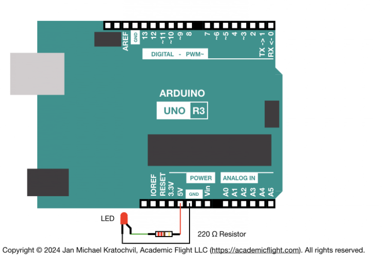
The Arduino Uno board consists of a power supply and data connection (USB), a microcontroller (long rectangular object in the image) which can run your programs written in Arduino programming language (a variant of C++), and a number of pins, which allow the connection of electronic circuits and which are grouped into power pins, analog pins, and digital pins. The Arduino Uno also has a built-in LED (not shown above).
We will be able to connect and power electronic circuits with these pins; for instance, the one depicted above consisting of a red LED (to emit light) and a resistor (to prevent the electric current from becoming too large), which are electronic components we will get to know in a later lesson.
Connections on the Arduino Uno
Board Power Supply and Data Connection
The Arduino Uno has a Type-B USB connector, from which it can be powered via a USB cable and which can be used to upload code onto the Arduino Uno to run, if this USB cable is attached to a computer on the other end. This USB cable can also be used to communicate between your computer and the Arduino, while the Arduino is running and executing its program (via the so called Serial Monitor). The USB connector can be seen in the image above depicted by the large silver rectangle on the upper left.
Unlike some other Arduino boards, the Arduino Uno does not have any Wi-Fi or Bluetooth LE capability, so the serial connection via the USB cable is the only way to communicate electronically with the Arduino Uno during runtime. (Of course, you can also attach an LCD, keypad, etc., for direct human interaction with the embedded system, if desired, which we will explore later.)
The Arduino Uno board also has many pins along its two longer sides, which we will discuss next.
Power Pins
At the bottom in the middle in the image above are the power pins. With these, the Arduino Uno can act as a voltage source for the electronic circuits which we will build together. These power pins work like the terminals of a battery and can power electronic circuits. The 5V pin is the main power pin of the Arduino Uno, providing 5 volts of positive voltage. You use it together with a GND pin to form a closed electric circuit, just like you would with the positive and negative terminals of a battery. Next to the 5V pin, you find two GND pins for exactly this purpose. In addition, you will find one more GND pin on the upper edge of the Arduino.
The 3.3V pin provides only 3.3 volts of positive voltage, instead of the 5 volts of the 5V pin. You would use this 3.3V pin, if you have components in your electronic circuit, which are not 5-volt-tolerant and which require a lower voltage. You would still close such an electric circuit by connecting the other end to one of the GND pins.
The “Vin” pin can be used as another 5-volt voltage supply pin, just like the 5V pin, when the Arduino Uno board is powered with a USB cable. But you could also use the Vin pin to power the Arduino Uno, if for some reason you do not want to or cannot connect a USB cable to power it.
Digital Input and Output Pins
Along the upper edge of the Arduino Uno board in the image above, to the right of another GND pin, you can see number of pins, labeled from 0 to 13. These pins are digital input and output pins. With the computer code we will write for the Arduino, we will be able to tell the Arduino Uno to apply a positive voltage to these pins (output), or to check if there is voltage on them (input). The pins marked with a tilde (~) are further capable of output using pulse-width modulation (PWM). All of this will be explained in the lessons of this course.
The Arduino Uno also has a built-in red LED, which we can turn on or off. This LED is on Digital Pin 13.
Analog Input Pins
Along the bottom edge of the Arduino Uno board, on the right, you see six analog input pins, labeled A0 through A5. These pins can measure, how much voltage is applied to them from the electronic circuit. (This is unlike the digital pins, which can only tell, if there is voltage or not, but they cannot record how much.) On the Arduino Uno, the analog pins are capable of input only, but there are other Arduino boards, which have analog output pins, where you can set how much voltage they will output.
Hardware Wrap-Up
The above must be a bit confusing for you right now, and that is ok. We will explain the use of all these pins in subsequent lessons of this course. The aim of this lesson was to introduce the different pins on the Arduino Uno to you and to show you, where they are. Use this lesson as a reference in the future, as a guide, where to find these pins on the Arduino Uno, as you work through the lessons of this course. This is not only the case, if you use a real Arduino Uno and electronic components (hardware), but also if you choose to use a simulator. Even on a simulator will still need to create electronic circuit diagrams and connect your circuits to the pins on the simulated Arduino Uno appropriately.