Glider Rating
Obtaining a glider rating can make you a more proficient and versatile pilot. Besides, flying without an engine is fun in its own right and environmentally friendly. It can also be highly competitive and performance oriented.
We offer glider instruction in owners’ sailplanes and through arrangements with glider flying clubs and commercial glider operators. Courses offered are an online glider pilot ground school, an add-on glider rating to your private or commercial pilot certificate, and training for flight instructor with a glider rating (CFI-G). We also offer spin training, and optional glider flights as part of our stability and control course, to emphasize the different flight characteristics of different aircraft. The above courses can be completed in a concentrated manner in just a few days.
Visitors interested in a mathematical treatment of gliding flight may also wish to consult our gliding flight article in the articles section of this website.
We unofficially/informally support the Civil Air Patrol (CAP): if you are a senior member or a cadet in CAP, you can receive glider instruction from us for free, if conducted as a CAP sortie in CAP aircraft.
What Makes Our Glider Training Stand Out
Laying proper foundations is very important for learning. Glider training is no exception. Below, we illustrate how Academic Flight’s diligent approach to flight dynamics in our glider courses leads to a deeper understanding of gliding flight, upon which advanced concepts can be built. We also offer a brief comparison to standard FAA training materials (FAA Glider Flying Handbook and Pilot’s Handbook of Aeronautical Knowledge).
As an introductory example, let us learn together how to draw the fundamental forces of flight properly and apply them to a glider in flight.
Procedure to Draw Aerodynamic Forces of Flight for a Glider
There are only two fundamental forces of flight acting on a glider:
- the weight force due to gravity (always pointing straight down towards the earth, no matter how the glider maneuvers) and
- the resultant aerodynamic force (RAF) due to the air hitting the airframe of the glider (it can point in any direction).
The RAF is conventionally (and by definition artificially!) decomposed into three components, which are defined as follows (this is a definition, and can therefore never be violated, no matter how the glider is maneuvering – unless one replaces it with a different definition):
- Drag is always parallel to the velocity vector of the glider.
- Lift is always perpendicular to the velocity vector of the glider. Because this requirement defines a whole 2D plane in 3D, it is further stipulated that lift be in the plane of symmetry of the glider. (The intersection of two 2D planes in 3D space is a line, so these two requirements together now define a unique direction.)
- Sideforce is perpendicular to lift and drag and of such magnitude, that lift, drag and sideforce together add up to the whole RAF.
The above is a very simple procedure, which one needs to follow diligently. (In the language of linear algebra, it is nothing else than a choice of orthogonal basis, with respect to which the RAF vector is expressed in three components.) We only still need to define the velocity vector of the glider, upon which the above definitions are based.
Velocity Vector of Aircraft
The velocity vector of a glider can be defined in one of two ways. One defines either:
- an airmass-relative velocity vector, which is pointing into the relative wind and indicates with which velocity (i.e. speed and direction) the glider is moving with respect to the air, or
- an inertial (or earth-relative) velocity vector, which describes the velocity of the glider moving with respect to the world. It is therefore tangential (parallel) to the flight path of the glider.
Both definitions have their reason for existence. For aerodynamics, the airmass-relative velocity vector is relevant, because what matters for the generation of aerodynamic forces is how the air hits the airframe. For the description of the glider flight path, on the other hand, the inertial velocity vector is relevant, because it describes the change in aircraft position with respect to the world.
When there is no wind with respect to the earth, i.e. in still air, the two definitions of velocity vector coincide. In this special case, lift is perpendicular to both relative wind and flight path, and drag parallel to both of them. However, in the general case where there is wind (e.g. rising or sinking air), the interpretation of lift and drag changes, based on which definition of velocity vector is used to construct them, as we shall see shortly. It is important to note that the RAF always remains the same, regardless of choice of velocity vector for the aerodynamic force decomposition into individual components.
All of the statements above are true not only for a glider, but for any aircraft. For airplanes, a third fundamental force comes into play: thrust, which is the propulsion force exerted by the power plant. (Below, when we use the word “thrust” occasionally in the sense of a force component forward along the flight path, we do so only because the FAA Glider Flying Handbook does so, and distinguish it from real thrust – absent for a glider – by the use of quotation marks.)
Equipped with the above procedure, we shall now tackle the two most basic situations encountered by the glider pilot: straight gliding flight in still air, and a glider climbing in straight flight in rising air.
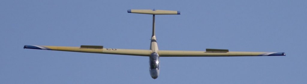
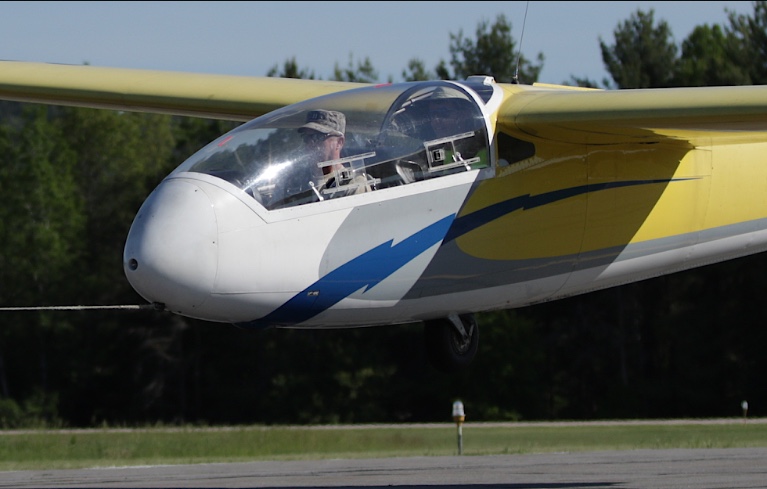
A LET L 23 Super-Blaník of the Civil Air Patrol during a steep landing approach with dive brakes extended. Springfield, VT.
Situation 1: Gliding Flight in Still Air
Forces Acting on a Glider
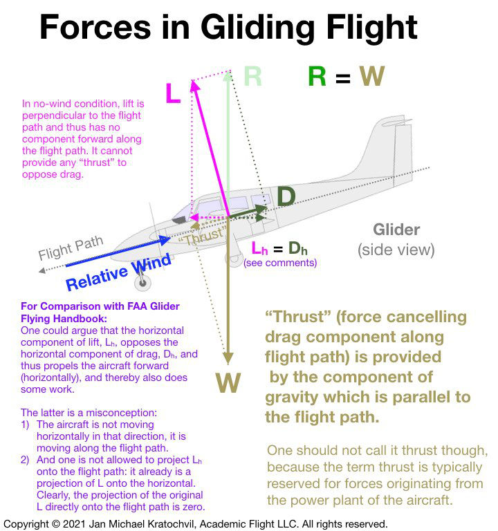
When one applies the above procedure diligently to straight gliding flight in still air, one arrives at the force diagram on the right. The weight force, W, points downwards towards the earth – a universal truth no matter how the aircraft is moving and maneuvering. There is no thrust, because the glider has no power plant. Since the motion is unaccelerated, all forces must add up to zero; therefore the RAF, R, must be equal and opposite to weight.
The only question that remains is, how do we decompose the RAF into lift, L, and drag, D? For this we must choose a velocity vector of the glider. Since the air is still, both definitions of velocity vector (airmass-relative and earth-relative) coincide, and we do not need to worry about distinguishing between them. The lift is perpendicular to both, the relative wind and the flight path. Drag is parallel to the relative wind and to the flight path.
Because lift is perpendicular to the flight path, it does not propel the aircraft forward along the flight path at all. The perpendicular projection of the lift vector onto the flight path is zero. If we want to abuse the word “thrust” as the force forward along the flight path opposing drag (as the FAA Glider Flying Handbook does), lift provides no “thrust” in this situation. “Thrust” is provided solely by the component of the weight force projected onto the flight path, and is equal and opposite to the drag force, resulting in no acceleration and a constant-speed glide.
Work (Energy)
Lift also creates no work in this situation. Remember from physics that work is force times distance, but only the force component parallel to the direction of motion. Since lift is perpendicular to the flight path here, i.e. to the direction of motion, it provides no work at all. It is the force of gravity that provides the work necessary to counteract the energy dissipated by the drag force (contrary to lift, drag points parallel to the flight path here). And this energy comes out of the potential energy of the aircraft, which decreases during the glide, while kinetic energy of the aircraft stays the same due to constant speed (the potential energy lost goes into the kinetic energy of the air molecules disturbed by the glider as it passes through the air).
There is a horizontal component of lift, Lh, pointing forward. And it is balanced by the horizontal component of drag. But the aircraft is not moving horizontally. It is moving along the flight path, to which the total lift L is perpendicular. It would incorrect to project Lh onto the flight path and to conclude that lift has a nonzero component along the flight path, because Lh is already a projection. If one did so, from the double projection one would erroneously obtain a nonzero component of lift forward along the flight path – in contradiction to the fact that if one projects the full original lift vector L, its projection onto the flight path is zero, since L is perpendicular to the flight path (one must be mindful not to make double projections). Note that the RAF itself has no horizontal component, neither forward nor backwards (and neither does weight). The RAF does have a backwards component along the inclined flight path, though, which is counteracted by an equal component of weight forward along the flight path.
Situation 2: Glider Climbing in Rising Air
Soaring – staying aloft in a glider without engine power for many hours – relies on the glider using various forms of rising air (called “lift” by the glider pilot – not to be confused with the lift of the wing): thermals, ridge lift, wave, convergence, etc. We shall ponder here the theoretically simplest of such cases, where the glider is flying straight in a uniformly rising airmass.
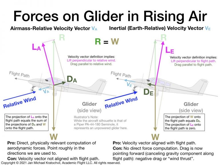
The rising airmass causes the relative wind to hit the aircraft from below the flight path. Therefore, because the airmass is moving now (rising) with respect to the earth and the relative wind and the flight path are not aligned, we must distinguish between the airmass-relative and the inertial (earth-relative) velocity vectors of the glider. The two diagrams below illustrate the two cases. The resultant aerodynamic force (RAF) acting on the glider is the sole force opposing gravity, and the two diagrams correspond to two different choices of decomposition of the RAF into lift and drag – both being valid with their own unique interpretation. The RAF does not change between the two pictures, regardless of choice of velocity vector, only the artificial decomposition of the RAF into lift and drag changes.
Airmass-Relative Velocity Vector
If we decompose the resultant aerodynamic force with respect to the airmass-relative velocity vector, lift becomes perpendicular to the relative wind and drag parallel to it.
This decomposition is very useful to compute lift and drag from aerodynamic equations. It is less useful to describe the motion/flightpath of the aircraft, because drag is now not pointing opposite the flight path, and not all of the drag inhibits forward motion of the aircraft along the flight path. A part of the drag force helps support the aircraft in the air, without causing energy loss. Unlike our previous example of gliding flight in still air, lift now does develop a forward component along the flight path, providing the “thrust” required to oppose the projection of the drag and weight forces backwards onto the flight path.
Inertial (Earth-Relative) Velocity Vector
If we want drag to point along the flight path, thinking of it as the force inhibiting forward progress, we must use the force decomposition of the RAF with respect to the inertial velocity vector. But now we experience a surprise: because lift is perpendicular to the flight path now, it cannot overcome the component of the weight force pointing backwards along the flight path, and it is also not doing any work. Therefore, drag must point forward! This is consistent with the further requirement that lift and drag must add up to the RAF. The RAF points vertically up to cancel the weight force vertically down. Because the lift vector is angled slightly backwards from the vertical in this picture, drag must point forward for the two to add up to the RAF.
This forward pointing (or negative) drag is not as strange as it may seem at first. It can be easily interpreted as “wind thrust” from the rising air, and when integrated over the flight path, gives the work the wind has done on the glider, as it climbs and gains potential energy. Something has to keep the glider aloft. Just like a sailboat is propelled by the drag the sails create with the wind blowing from the back (assuming old-fashioned sails), the glider is kept aloft by the wind. Because the wings are highly efficient airfoils, the wind does not have to come from the back, as the airfoil can accept wind mostly from the front (as long as it is still slightly angled from the bottom) to create the required force. The wind is created mostly by the motion of the glider with respect to the earth and to a lesser (but very important) extent from the rising air. Lift is in this picture by definition always perpendicular to the flight path and is therefore the component of the RAF that does no work at all, using the same argument as in the still air case we discussed previously.
The aerodynamic interpretation of lift and drag (with respect to the airfoil and aerodynamics) has disappeared in this picture. For that, one must use the first picture, using the airmass-relative velocity vector.
Comparison to FAA Handbooks
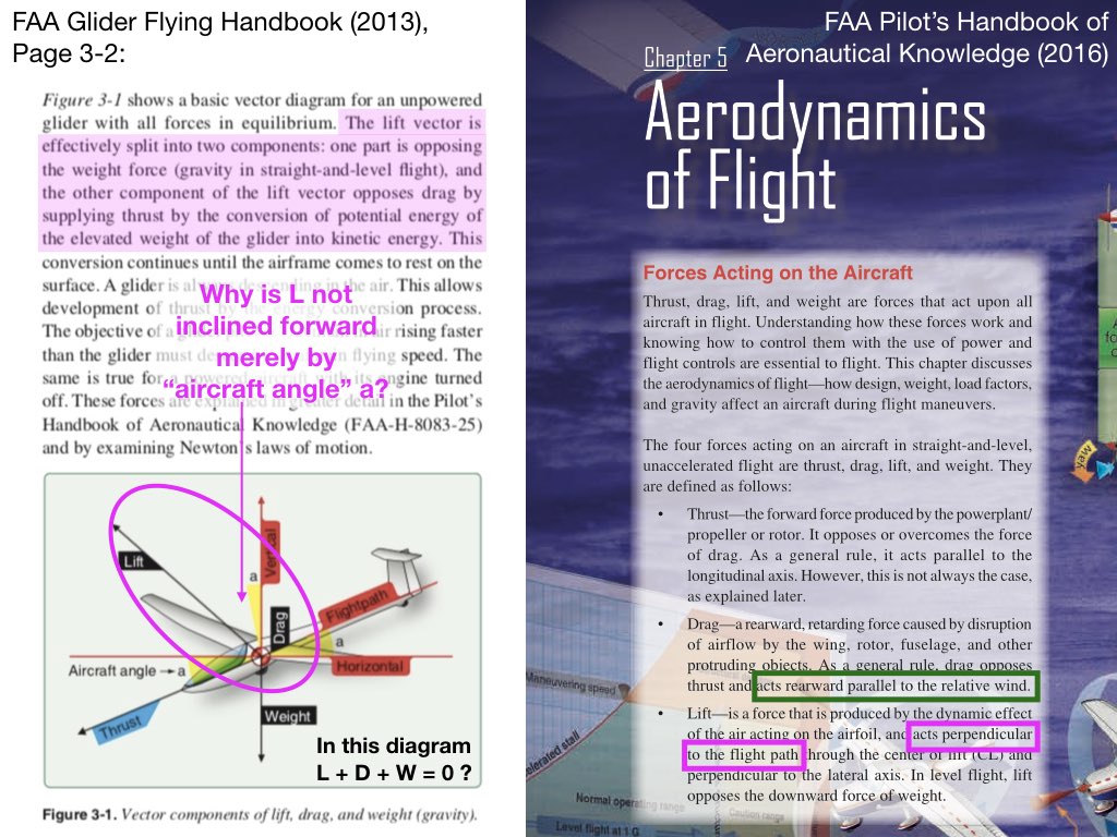
FAA handbooks seem to struggle a bit with the forces of flight, especially as they relate to gliders. In the left half of the image above, which is taken from the FAA Glider Flying Handbook (2013), the lift vector is angled too far forward and is misinterpreted in the text as having a component along the direction of flight (projection onto the flight path), which is then labeled “thrust”. As we have seen in our previous discussion, in still air lift is always unambiguously perpendicular to both relative wind and flight path and has therefore no component along the flight path in the direction labeled as “thrust”. The excessively forward pointing velocity vector also ends up being too long (in an attempt to create this forward “thrust”), resulting in the lift, drag, and weight forces of the diagram not adding up to zero, which would be required for straight, unaccelerated gliding flight.
The authors of the FAA Pilot’s Handbook of Aeronautical Knowledge (2016) (PHAK) fare much better and get it almost correctly (see right half of the above image), but they end up mixing the airmass-relative and inertial (earth-relative) velocity vector pictures in the definition of lift and drag: they define drag based on the airmass-relative velocity vector and lift based on the inertial velocity vector. This is fine in still air, but inconsistent in the presence of wind, and can lead to crazy force diagrams, if the air is moving. The reader should also be aware that there is no way to get the drag vector to point rearward for a glider in climbing flight in rising air, if one chooses that the lift vector be manifestly defined as being perpendicular to the flight path.
A correct drawing of forces and moments is a prerequisite for a meaningful discussion of more challenging flight maneuvers, such as spins and high-angle-of-attack situations in general, which can lead to loss of control. Contemplating glider flight offers a wonderful opportunity for a deeper understanding of flight dynamics and for airmanship development.
References
To commence or continue your glider training, we suggest you consult some of the following references:
- “Glider Flying Handbook,” FAA-H-8083-13A, U.S. Department of Transportation, Federal Aviation Administration, Flight Standards Service, Washington, D.C., 2013:
https://www.faa.gov/regulations_policies/handbooks_manuals/aviation/glider_handbook/media/faa-h-8083-13a.pdf - “Pilot’s Handbook of Aeronautical Knowledge,” FAA-H-8083-25B, U.S. Department of Transportation, Federal Aviation Administration, Flight Standards Service, Washington, D.C., 2016:
https://www.faa.gov/regulations_policies/handbooks_manuals/aviation/phak/
- “Private Pilot Practical Test Standards for Glider,” FAA-S-8081-22 with Change 1, U.S. Department of Transportation, Federal Aviation Administration, Flight Standards Service, Washington, D.C., April 1999 (September 2021):
https://www.faa.gov/training_testing/testing/test_standards/media/FAA-S-8081-22.pdf - “Commercial Pilot Practical Test Standards for Glider,” FAA-S-8081-23A with Changes 1 and 2, U.S. Department of Transportation, Federal Aviation Administration, Flight Standards Service, Washington, D.C., November 2006 (September 2014):
https://www.faa.gov/training_testing/testing/test_standards/media/FAA-S-8081-23A.pdf - “Flight Instructor Practical Test Standards for Glider,” FAA-S-8081-8B, U.S. Department of Transportation, Federal Aviation Administration, Flight Standards Service, Washington, D.C., October 2006:
https://www.faa.gov/training_testing/testing/test_standards/media/FAA-S-8081-8B.pdf
- Soaring Society of America:
https://www.ssa.org
(Offers a map of glider clubs and commercial operators across the United States, awards accomplishment badges, organizes soaring competitions, etc.) - Dr. John (Jack) Glendening’s Website DrJack:
http://www.drjack.info
(Forecasting of soaring conditions, divided by regions across the United States)
For a fascinating introduction to competitive cross-country soaring and an in-depth analysis of a soaring competition flight:
- Clemens Ceipek (chessintheair), analysis of a flight at the 18-meter National Soaring Championships 2021 in Nephi, UT:
https://www.youtube.com/watch?v=Tj2sv6eQRTU