Introduction to Embedded Systems
Controlling a Digital Pin (Output)
In an earlier lesson, we created a simple electronic circuit with an LED and resistor to turn on the LED. In that lesson, we used the Arduino Uno essentially merely as a voltage source (like a battery), providing positive and negative voltage via the 5V and GND pins. While the LED did shine successfully, we had no way of turning it on or off other than by disconnecting the circuit or unplugging the Arduino Uno from its USB power source.
In this lesson, we want to control whether the LED shines or not with the Arduino Uno via a computer program (which we compile and upload to the Arduino with the Arduino IDE software, as described in an earlier lesson). In order to accomplish this, we need to change the electronic circuit diagram a little bit. Instead of connecting one of the ends of the circuit to the 5V power pin, we shall connect it instead to one of the digital pins. In the diagram and code example below, we choose Digital Pin 6 for this, but we could use any of the other 12.
Example of Controlling a Digital Pin Output
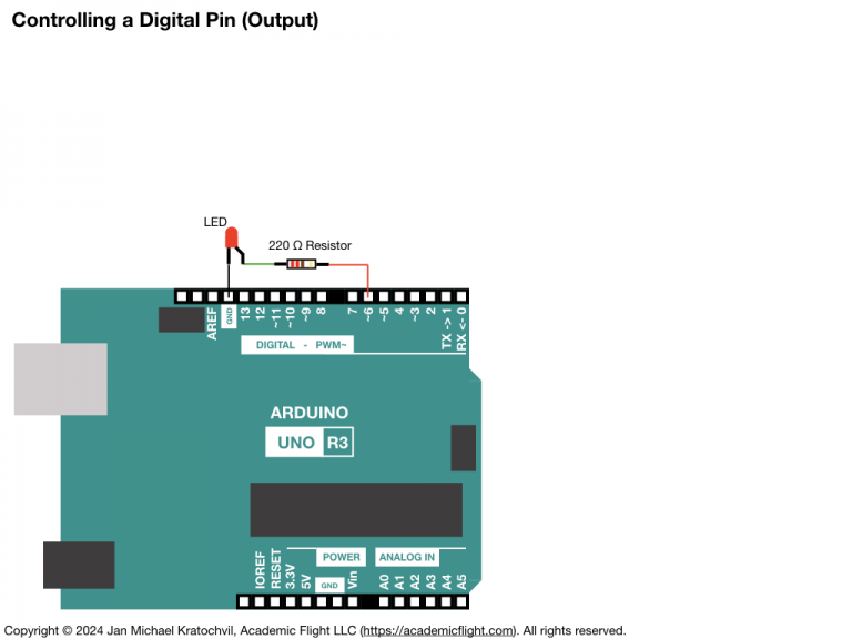
Electronic Circuit Diagram
In the diagram below, Digital Pin 6 takes on the role of the power source, providing 5V (which used to be provided by the 5V pin). We will be able to turn on and off this digital pin with the Arduino programming language code in the sketch.ino file.
Code (sketch.ino)
The Arduino programming language code of the sketch.ino file for the Arduino IDE software for this task is below.
#define PIN 6

void setup() {
  // put your setup code here, to run once:

  // Designate digital pin PIN to be an output pin:
  pinMode(PIN, OUTPUT);

}

void loop() {
  // put your main code here, to run repeatedly:

  // Turn of digital pin PIN:
  digitalWrite(PIN, LOW);
  delay(500);
  // Turn on (apply positive voltage) to digital pin PIN:
  digitalWrite(PIN, HIGH);
  delay(500);
}
The definition at the beginning does not define a variable. Instead, it instructs the compiler to replace “PIN” in the code everywhere by the number 6. It is, as if we deleted “PIN” in the code everywhere and wrote 6 in its place instead.
The built-in pinMode() function tells the microcontroller, whether a pin is going to be an output pin or an input pin. The first argument of the function is the pin number. Digital pins are simply numbered by the numbers on the Arduino board (analog pins get an A before their number). The second argument of the pinMode() function can take the values OUTPUT, INPUT, or INPUT_PULLUP, which determines if the pin will be an output or input pin.
If the pin is designated to be an output pin, the code will later be able to set its voltage to on or off using the digitalWrite() function. If, on the other hand, it is an input bin, the digitalRead() function will be able to determine, if there is voltage on the pin or not (due to some external circuit). In this sketch, we will only use the former; the latter case is treated in the next lesson.
The built-in digitalWrite() function controls the voltage of a digital output pin to be either on or off. Its first argument is the pin number. Its second argument is either HIGH (in which case full positive voltage is applied and the pin is considered to be on) or LOW (in which case no voltage is applied, and the pin is considered to be off).
The delay() function pauses the code for the number of milliseconds specified in its argument. We will discuss runtime related functions later in a separate lesson. We use it here only to set the blinking frequency of the LED.