Short Course: PID Controller for Quadrotor
Description
In this short course, you will learn the basic concepts of writing a Proportional-Integral-Derivative (PID) controller for a quadrotor (a common drone with four rotors). The code will be written in python as a class within a provided Jupyter notebook document that simulates the basic physics of a quadrotor without any aerodynamics and without any event-driven programming (writing a code that can be installed on an actual drone goes beyond this introductory short course).
Prerequisites
Preferred prerequisites to take this course are familiarity with Python. Having knowledge roughly equivalent to our Stability and Control I course is also highly beneficial, but if you have a quick grasp of mathematics and the ability to learn about Euler angles, body rates, and the equations of motion on the fly, you may attend without it (there will be a brief review). You should also install the Jupyter environment on your computer before taking the course (contact us if you need any assistance – on a Mac we recommend you use the free Individual Edition of Anaconda for this, also available for other operating systems).
Cost and Duration
We currently offer this course for a deeply discounted rate of $50 as a contribution to the autonomous flight community. The course consists of a few hours of instruction (up to half a day, depending on the background level of the participants), after which the participants write their own PID controller as an exercise independently (assistance is provided if needed). The class is held in irregular intervals on weekends, when a sufficient number of people has signed up. To put yourself on the list, please contact us.
Illustrations
The examples below show some behavioral aspects of PID controllers we will encounter during the course.
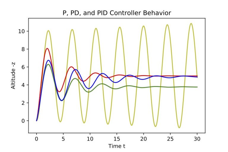
Fundamental Behavior of a PID Controller in 1D
Illustration of the performance of a PID controller of a drone: The plot shows the change in altitude of an autonomously flying drone as a function of time. The done starts at zero from rest, and attempts to reach a target altitude of 5 meters, using an autonomous control algorithm. The yellow curve depicts a drone using only a P (proportional) controller, and exhibits undamped oscillations around the target altitude: The drone overshoots its target altitude each time, because it does not understand that it needs to reduce its vertical velocity as it approaches the target altitude. This can be corrected if one includes a velocity dependent derivative term, making it a PD controller (red). However, if a misestimation of drone mass exists, a PD controller would bring the drone the to wrong final altitude (green). Including an integral term in the control algorithm (PID controller) allows the drone to reach the correct target altitude even with a mass misestimate (blue).
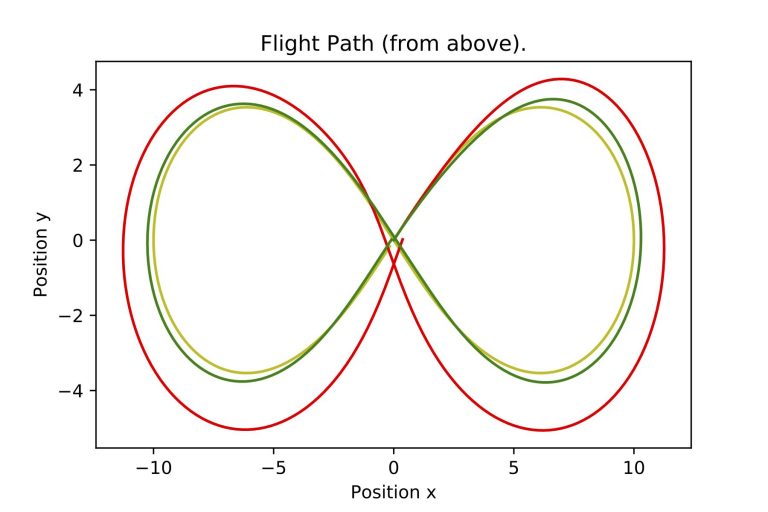
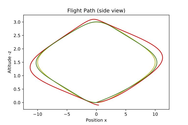
Feedforward Term
The two images on the left show a drone following a desired flight path shaped like an altitude-modulated lemniscate. The top image shows a top view of the flight path, the bottom image shows a side view. The highest point of the flight path is in the middle of the maneuver. In the images, the drone completes one loop around the path, starting in the middle, and heading off in positive x and y direction (to the upper right) with increasing altitude.
The red curve shows the actual flight path of the drone, trying to follow the desired flight path (yellow) using a 3-axis PID controller. The drone takes off in the correct direction, following the flight path initially, but then struggles to anticipate the first turn to the right and is carried to the outside of the turn. An altitude deviation occurs as well (see lower image). This is because the drone knows nothing about how the path is changing ahead and only reacts to deviations from its present position to the target flight path, thus failing to anticipate course changes.
If one includes a feedforward term in the PID controller (green), the drone is capable to anticipate direction and altitude changes, and manages to follow the yellow desired target flight path much more accurately.
The difference in this example was intentionally exacerbated for illustrative purposes. It would have been possible to tune the gain parameters of the PID controller better, to have the red curve match the yellow one much more closely.