PPGS 2023-2024, Lecture 4: Physical and Mathematical Foundations of Flight Dynamics – Selected Presentation Slides
Introduction: Reading Assignment
Lecture 4 is a reading assignment; it will not actually be held in person. It is study material for the students during the lecturer’s absence. This lecture lays the conceptual foundation for the weight and balance calculations that will be discussed in Lecture 5, as well as the flight dynamics in Lecture 6 (longitudinal stability) and more advanced flight maneuvers covered in the spring (such as spins). Therefore, a good understanding is important. The more time you put into studying the set of slides below, and the more questions you ask about them during subsequent in-person lectures, the easier future lessons will come to you.
The lecture slides below cover four topics:
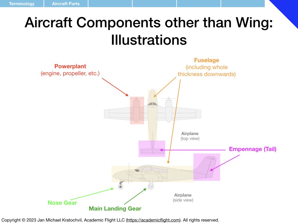
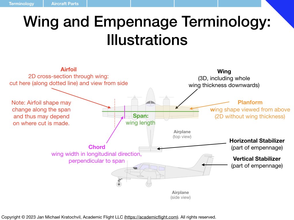
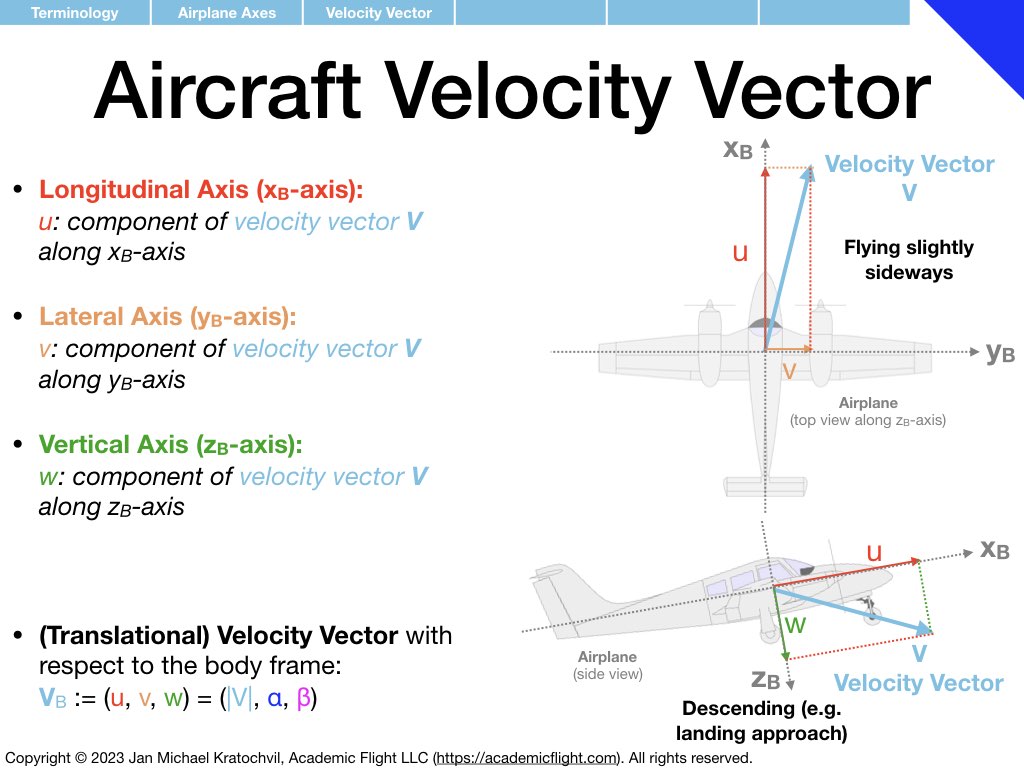
- Aircraft Terminology (names and definitions of aircraft parts, axes, moments, vectors, angles, etc.)
- Kinematics – Description of Attitude and Motion (Axis Systems, 3-2-1 Euler Angles, Rotation Formalisms)
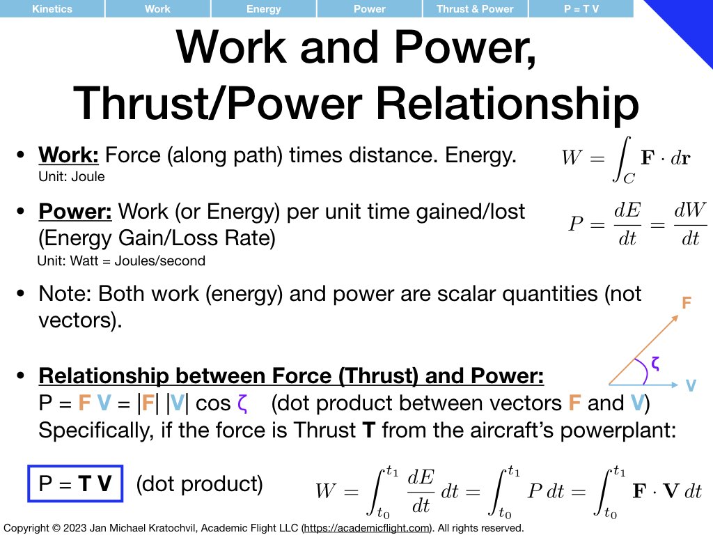
- Kinetics – Physics of Motion (Translational and Rotational Physics)
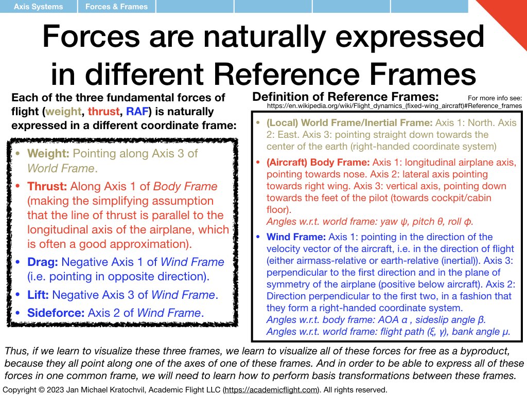
- Forces and Moments: Physics Foundations for Weight and Balance and Longitudinal Stability of Aircraft
Forces and moments, of course, belong into the topics of kinetics. But in that chapter we treat forces and moments (which are “rotational forces”) just as independent black boxes, an reveal only in the Forces and Moments Appendix (the fourth sets of slides), how forces actually generate moments.
As usual, slides with blue upper corners you should make a dedicated effort to understand. Slides with red corners cover concepts you may want to ponder sometime in the near (or later) future (but can probably be understood right away). And finally, black-corner slides are introductions to highly technical content for students who aspire to become experts one day (these slides may require intense thought or even consultation of external resources to be understood properly).
Terminology
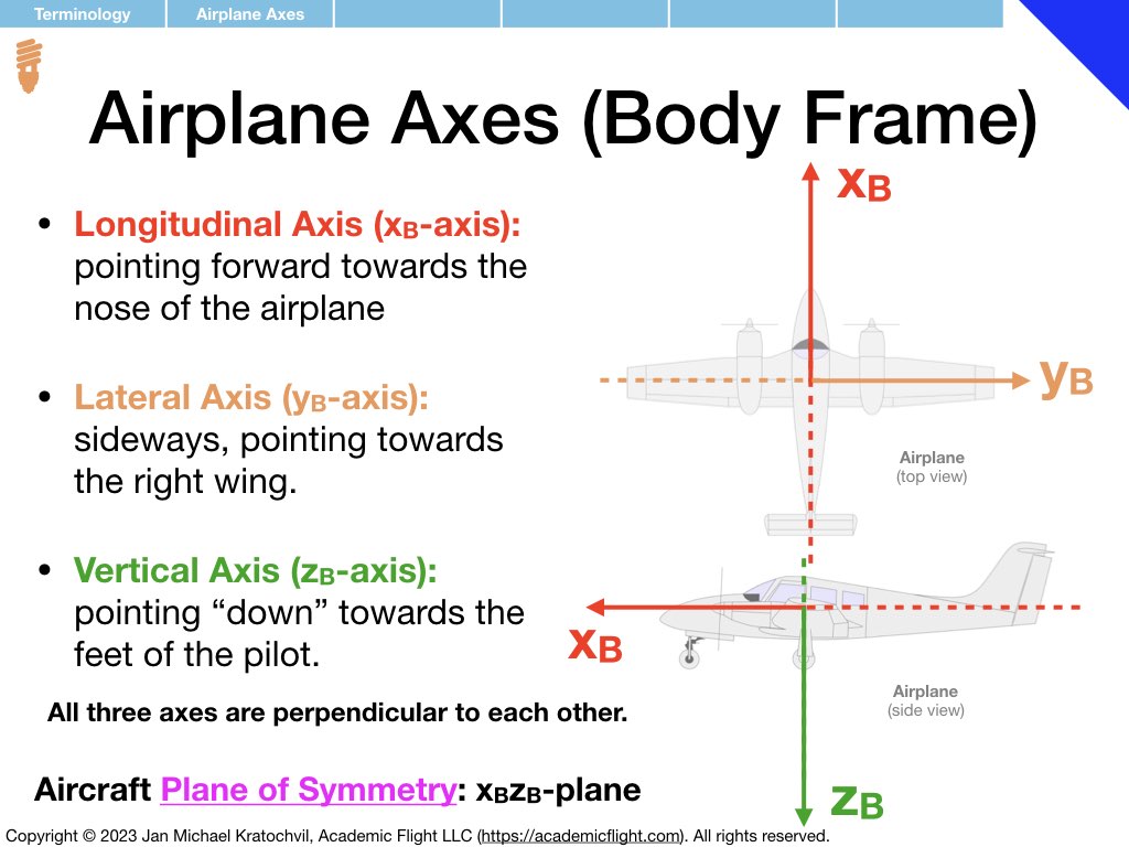
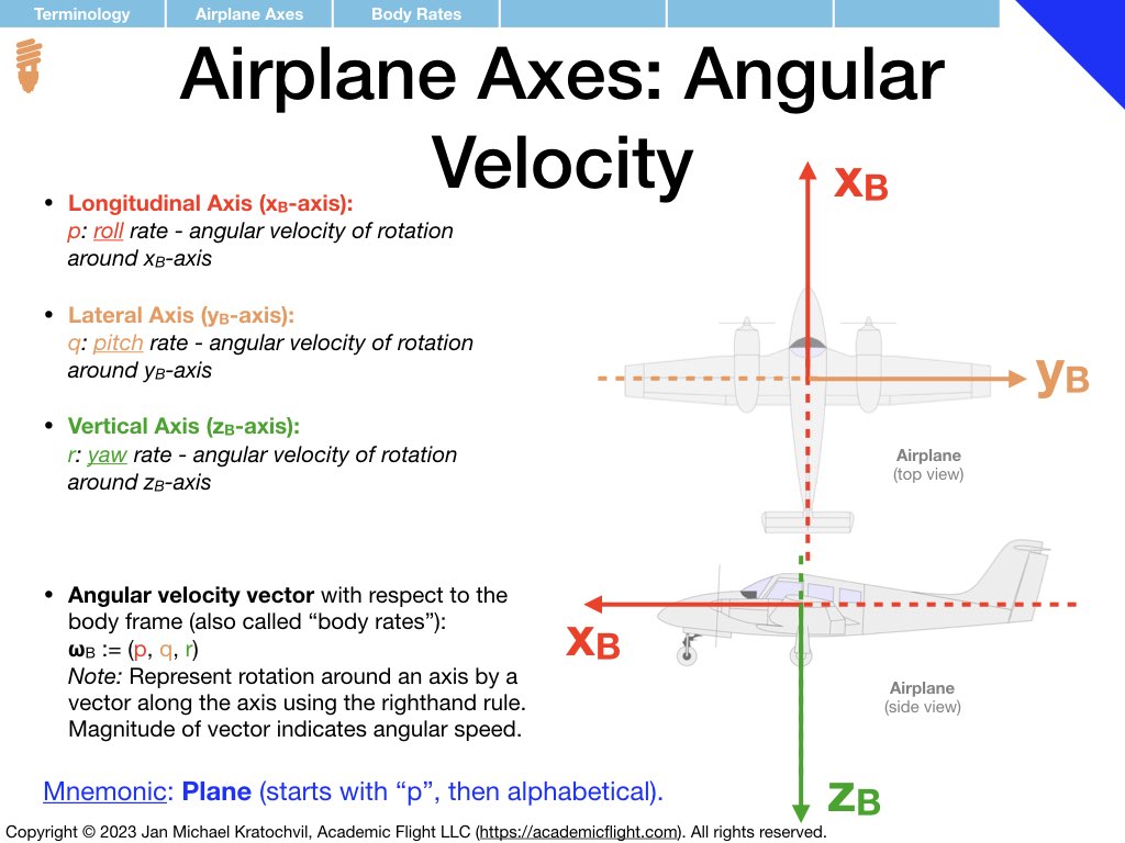
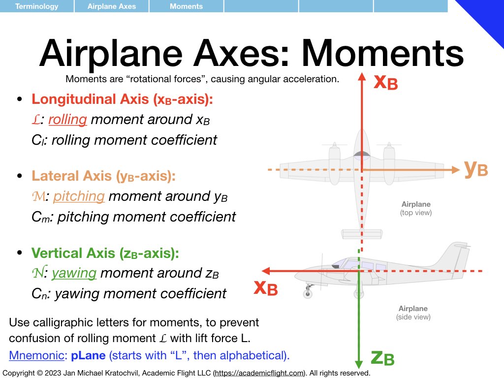
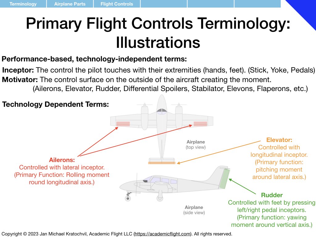
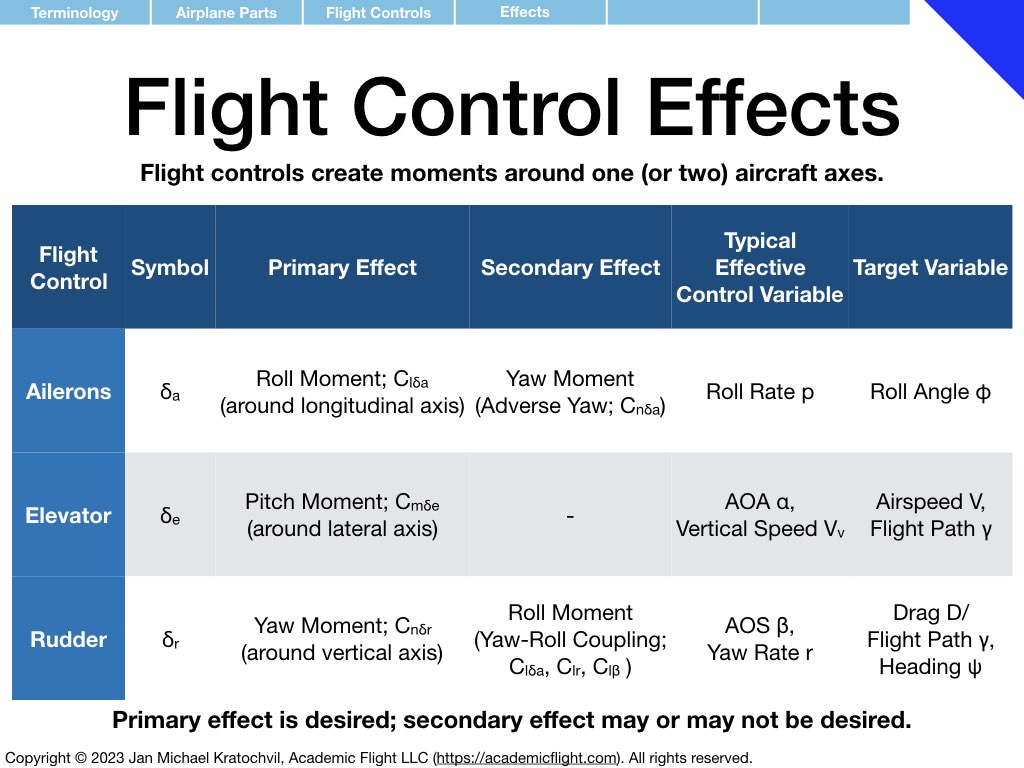
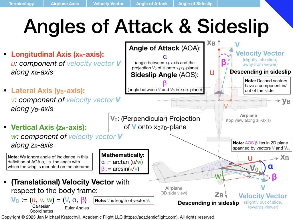
In the next few slides we define various terminology used in and around the aircraft, such as aircraft parts, control surfaces, aircraft axes as well as rotation rates and moments around them. Angle of attack and angle of sideslip are also defined – precisely, in the presence of both of them simultaneously. Defining a common vocabulary for quantities frequently used makes communication more efficient, precise, and avoids misunderstandings and misconceptions.
Much of the terminology introduced below you should become familiar with. Also try to remember over time the symbols used for the different physical quantities that appear (mnemonics for easy ways to remember some of them are provided). But do not spend extra time on memorization, these symbols will become second nature to you with use over time.
Kinematics (Description of Aircraft Motion)
Kinematics deals with the description or motion, without any of the physics involved. Physical concepts of rotational motion, such as moments (rotational forces), the inertia tensor with its moments of inertia and products of inertia, and associated equations of motion (the rotational physics counterpart of \(\mathbf{F} = m \mathbf{a}\)) are left on the bench for now. We will study these later.
For now, all we will consider is the rotational motion itself. The simplest question we can ask is, how do we describe aircraft attitude. For this, we need a rotation formalism – a description of attitude using some parameters.
Why do we need a Rotation Formalism for Attitude Description?
Question: But why do we need a rotation formalism? Can’t I just say that my wings aren’t level and that my nose is above the horizon? Answer: Regarding the wings, you can probably see that it is a rotation that puts them into a non-level attitude. As for the nose, it is not really “above” the horizon; it just looks that way looking out of the windshield. In reality the aircraft is “pitched up”, i.e. rotated up. Thus attitude changes really are rotations.
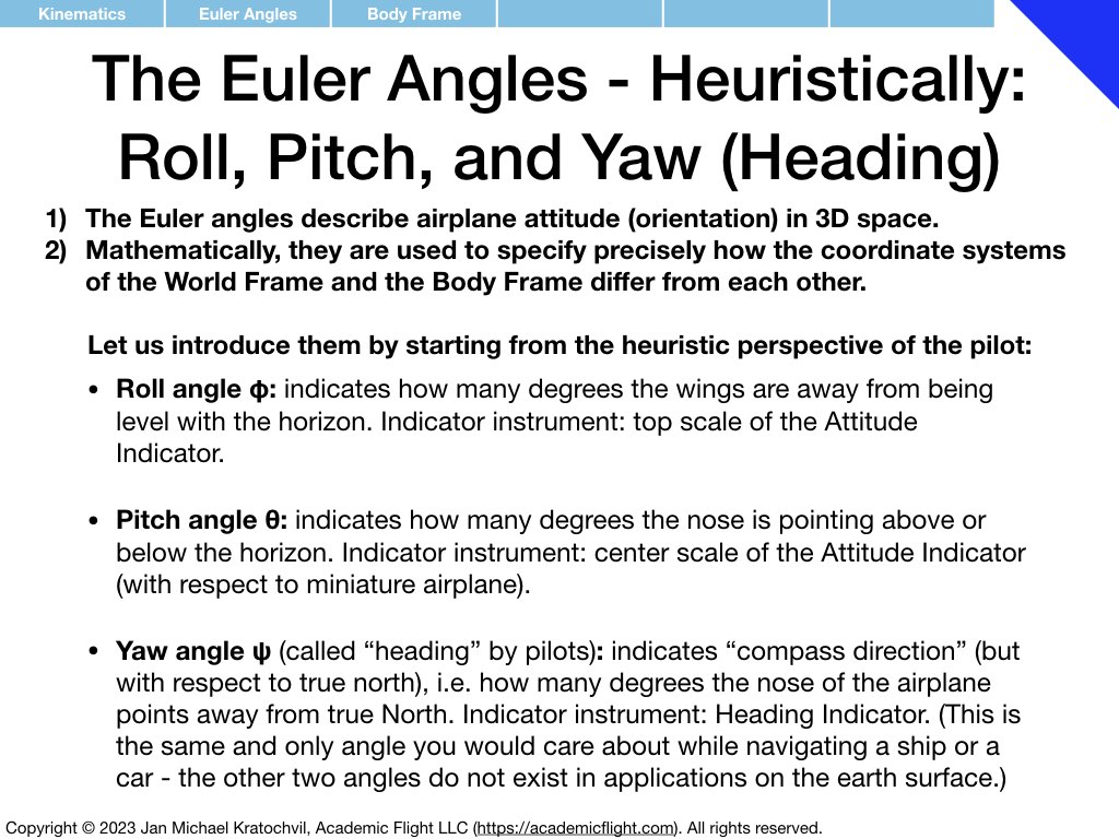
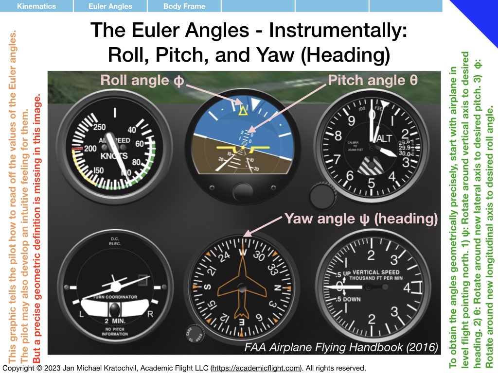
Question: Why do we need to introduce and parameters to describe attitude? Can’t I just read off the aircraft instruments? Answer: What do you think the aircraft instruments are telling you? Values of parameters – heading, roll angle and pitch angle are parameters; they are variables to which you assign a number based on what you read off on the aircraft instruments. Thus, implicitly, whether you are realizing it or not, you are using a rotation formalism with a suitable (intuitive) parametrization, when you think about aircraft attitude.
It is best to think formally about what you think about, rather than just having a diffuse feeling about what you are thinking about. Otherwise you might end up like the German Coast Guard in this video.
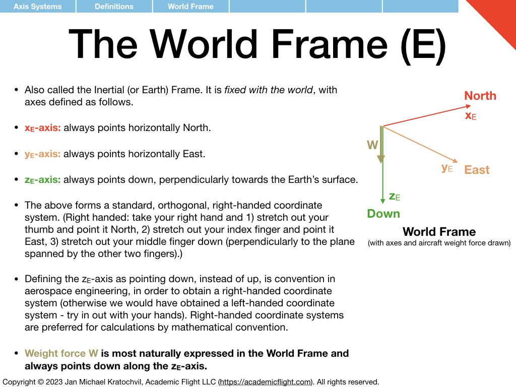
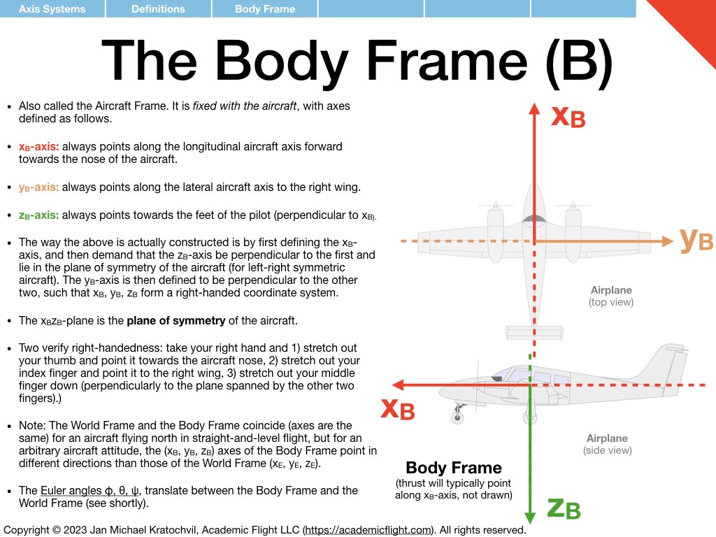
Axis Systems (Reference Frames)
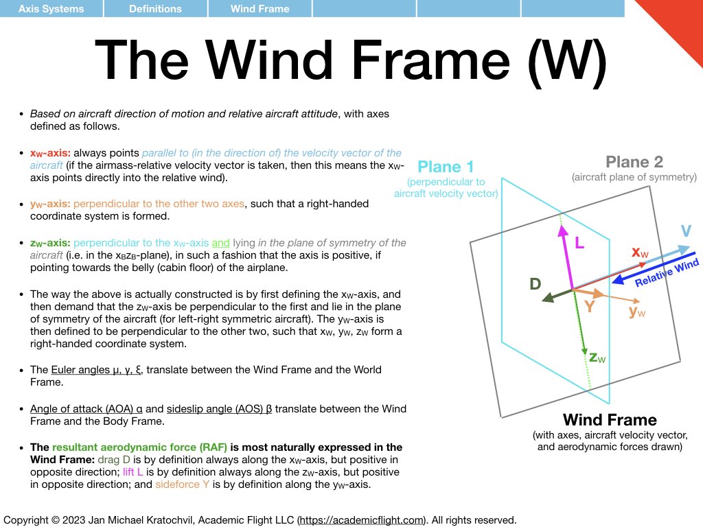
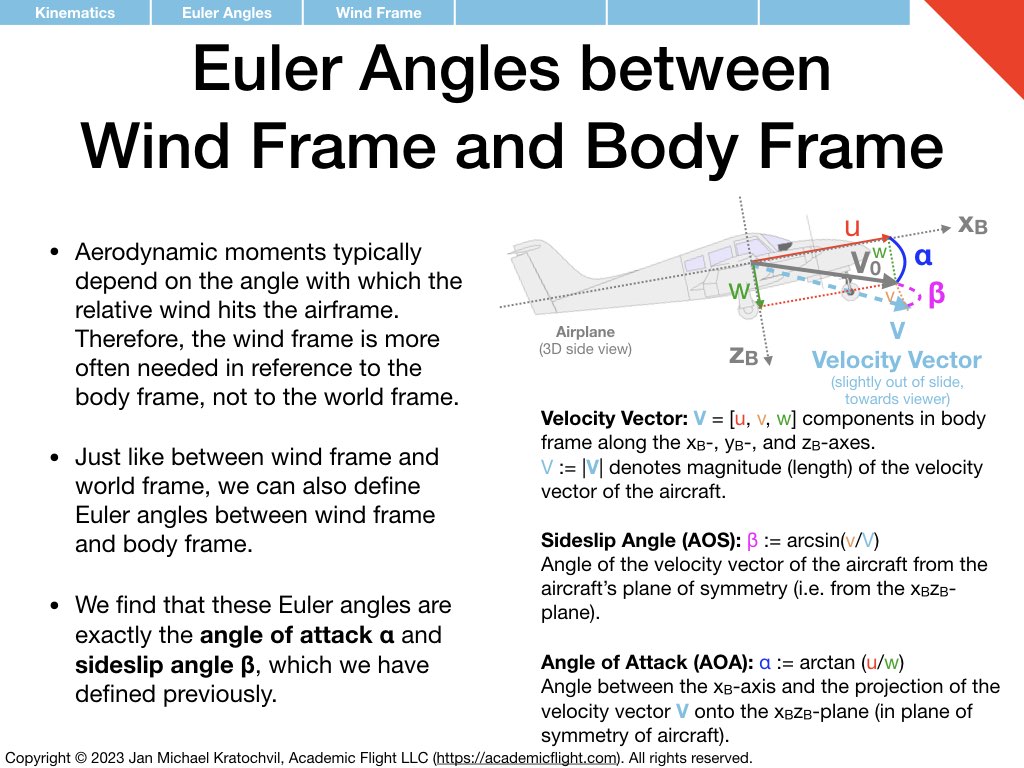
Before the rotation formalism can take any foothold, we need to define directions in space: with respect to the Earth, with respect to the aircraft, with respect to the airflow, etc. We saw this before in aerodynamics: we were able to introduce the angle of attack (AOA) \(\alpha\) to describe the orientation of an object (airfoil) in space, with respect to the airflow, but we needed to introduce the direction of the relative wind first as a reference direction, and we also needed to define a reference direction on the airfoil, which we called the chord line. Without defining these two reference directions first, the AOA would have been meaningless. We had to state, the AOA is the angle between what. It is this what, which we now define in three-dimensional space, when we discuss axis systems.
Attitude Parametrization using 3-2-1 Euler Angles
We need a clear, well-defined description of aircraft attitude, which leaves no room for ambiguity. For this, we need a rotation formalism in three dimensions, which manages to describe any aircraft attitude as a 3D rotation from some reference attitude (the latter is usually taken to be an airplane pointing north, wings level, with its nose on the horizon).
Many different rotation formalisms exist, including the rotation matrix (see linear algebra), various Euler angle definitions, the axis-angle formalism (principal rotation vector), quaternions, and several others. We shall introduce one of them here fairly briefly.
We choose the 3-2-1 Euler angle formalism for several reasons:
- It is commonly used in aerospace engineering for attitude descriptions of the kind of atmospheric aircraft we are considering in this course.
- It allows humans to visualize the attitude of the aircraft easily.
- The standard aircraft instruments (attitude indicator and heading indicator) indicate the three parameters of this formalism directly: we can read off their values directly from our instruments in the aircraft.
One of the most attractive features, which make this rotation formalism so popular, is its ease of visualization of aircraft attitude (further below we will encounter a different formalism, which is computationally more convenient, but impossible for humans to visualize). Visualization is tremendously important for pilots, who need to make decisions in real time. The rotation formalism also has some drawbacks, e.g. a coordinate singularity for an airplane flying vertically straight up into the sky, but we find ourselves relatively rarely in such a situation in our applications.
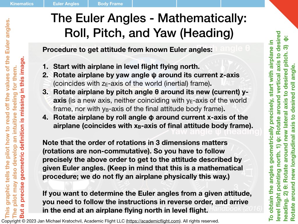
The above preference is clearly application specific. If we were studying the orbital motions of satellites, we may find that 3-1-3 Euler angles are more convenient – a close, but distinctly different relative of the 3-2-1 Euler angles we will be using here. The 3-2-1 Euler angles are called 3-2-1, because – as you can see from the slides below – we first rotate around the third axis, then around the (new) second axis, and then around the (again new) first axis.

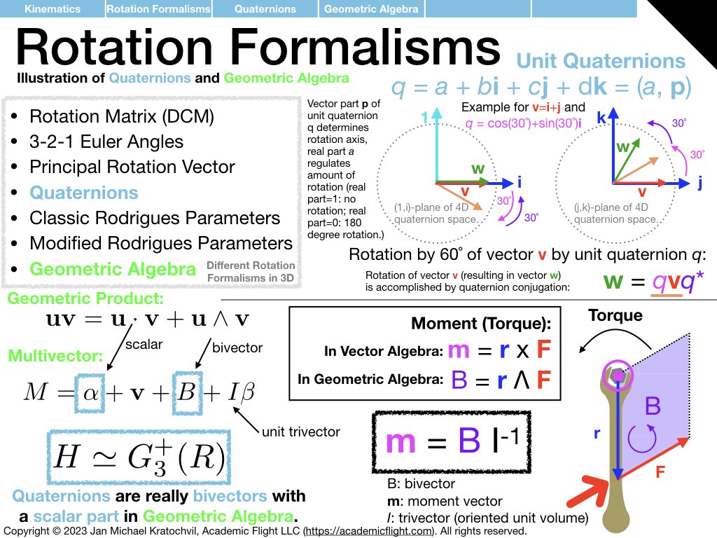
Other Rotation Formalisms in 3D
3-2-1 Euler angles are not the only rotation formalism in 3 dimensions. There are many others. Unit quaternion conjugation provides a very elegant and computationally efficient way of computing rotations, while avoiding the coordinate singularity, which Euler angles exhibit. It is not as intuitive though – neither for attitude visualization nor for computations.
Even less visualization intuitive, but very straightforward mathematically (basic linear algebra) is the rotation matrix formalism. In fact, this is the “mother of rotation formalisms,” which also acts as a universal translation tool between all the others: for any rotation formalism out there, there is always a procedure to compute the rotation matrix, and also reversely to infer the parameters of your particular rotation formalism, if the rotation matrix is know.
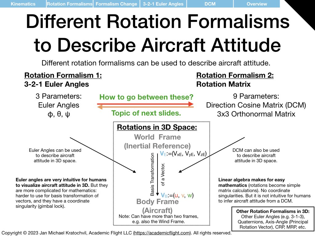
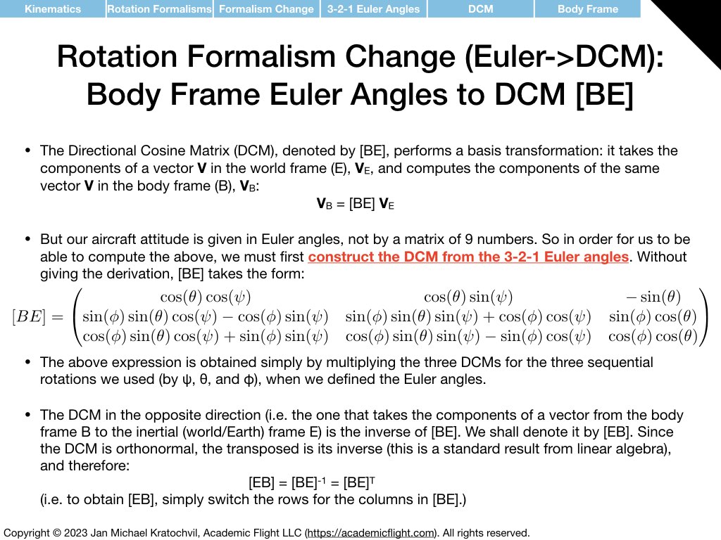
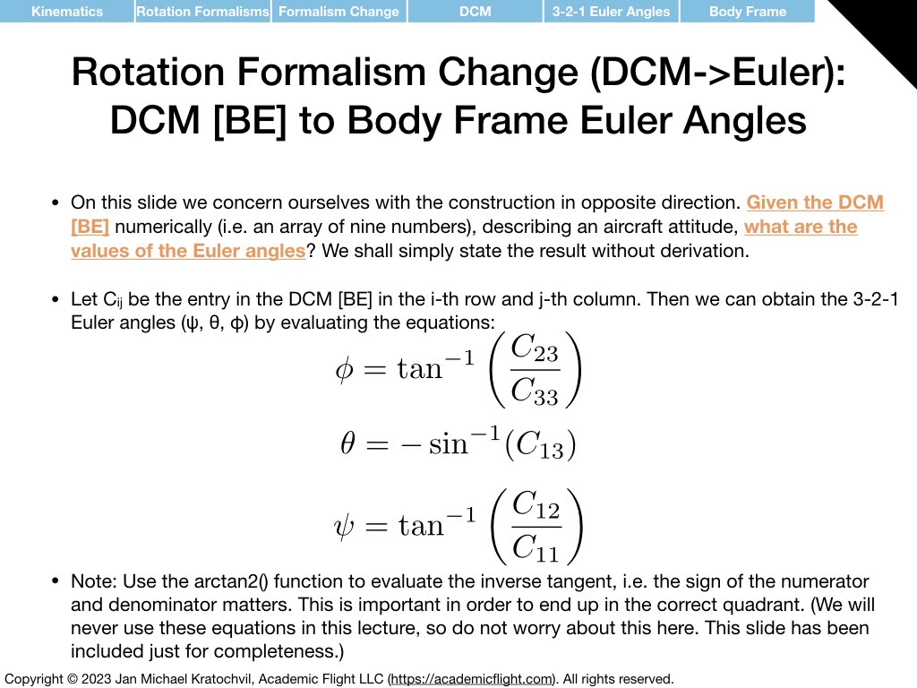
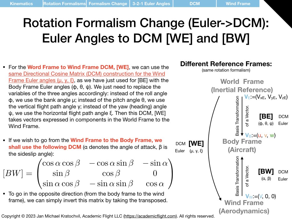
As an illustration that there are different rotation formalism and that one can translate between them, we therefore explain below how to translate between 3-2-1 Euler angles and the rotation matrix formalism. We show how to compute the rotation matrix (also called Direction Cosine Matrix (DCM)), if the 3-2-1 Euler angles are known. And we also explain the opposite direction, how we can compute the 3-2-1 Euler angles, if the rotation matrix is know. (With the rotation matrix you can rotate any vector or perform a basis transformation of the components of a fixed vector between two different reference frames, as is explained in our Linear Algebra Primer.)
This is certainly an advanced topic for pilots, who are particularly engineering minded. You can safely skip this part, if you like.
A more detailed description of these and other rotation formalisms in three dimensions is given in our article series on 6 popular rotation formalisms in kinematics.
Additionally, if you would like to learn more about the description of attitude and motion, an excellent course on rotation formalisms for this purpose is taught by Prof. Hanspeter Schaub on Coursera, “Kinematics: Describing the Motions of Spacecraft”, which he teaches at the University of Colorado Boulder. You can audit the course on Coursera for free – or even get a completion certificate, if you pay for registration.
Kinetics (also called Dynamics – Physics of Translational and Rotational Motion)
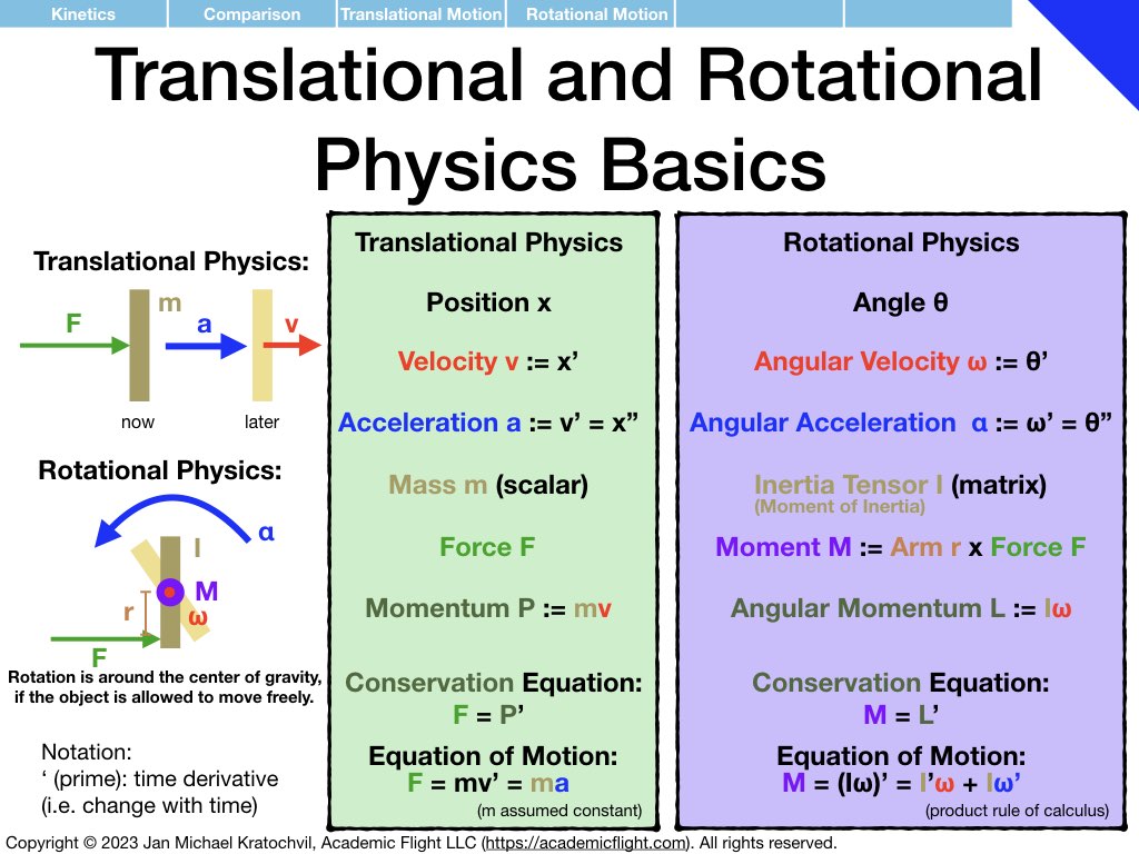
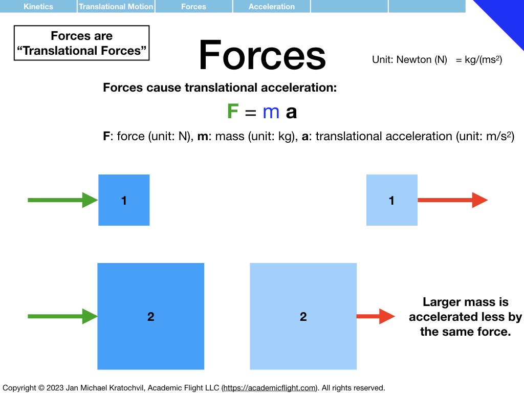
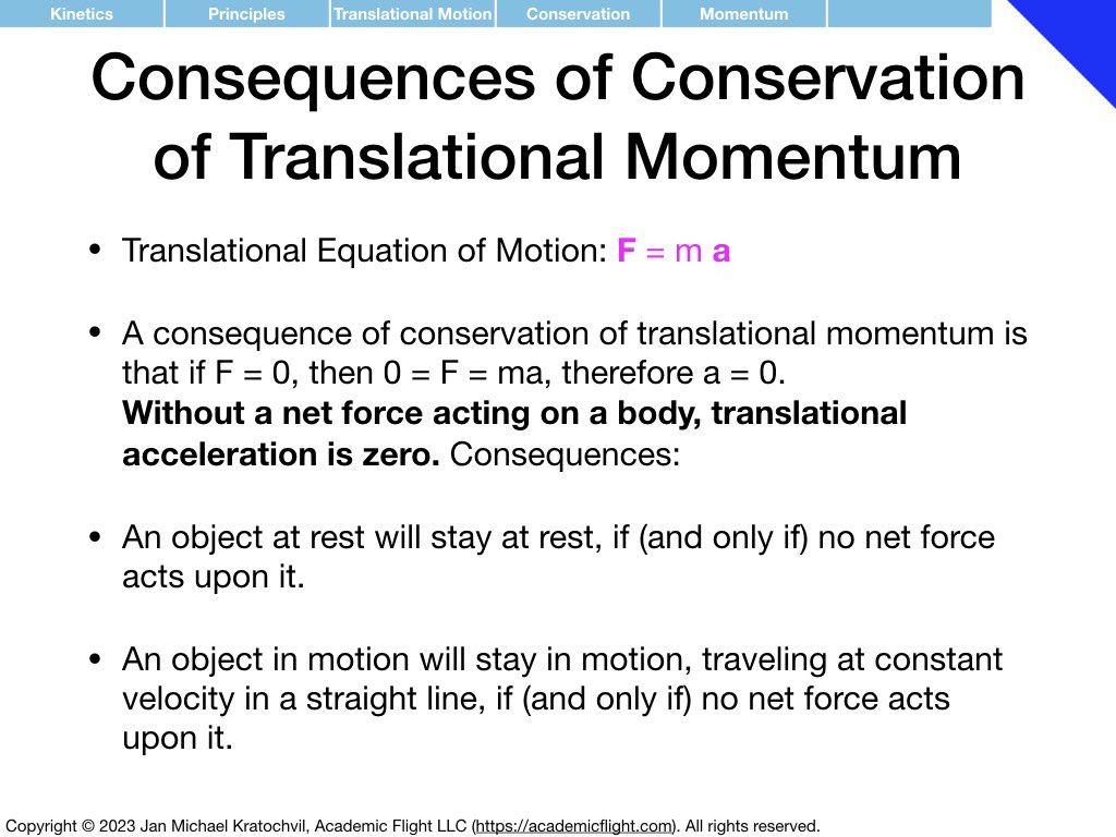
The student is probably more familiar with translational physics and the equation \(\mathbf{F} = m\mathbf{a}\) than with rotational physics. But as a pilot, we need to understand rotational physics, too: a very basic, rudimentary knowledge is required for weight and balance calculations and the understanding of longitudinal stability of an aircraft. More advanced knowledge of rotational physics – including so called inertial coupling and the properties of the inertia tensor – is required to understand spins.
Luckily, rotational physics has many similarities to translational physics, which lets us build on existing knowledge and drawing analogies between the two. But rotational physics also has some differences – complications actually -, which make rotational physics in its full glory much richer, yet also more difficult. In the slides below we discuss the very basics of physics of translational and rotational motion in a simple, approachable way.
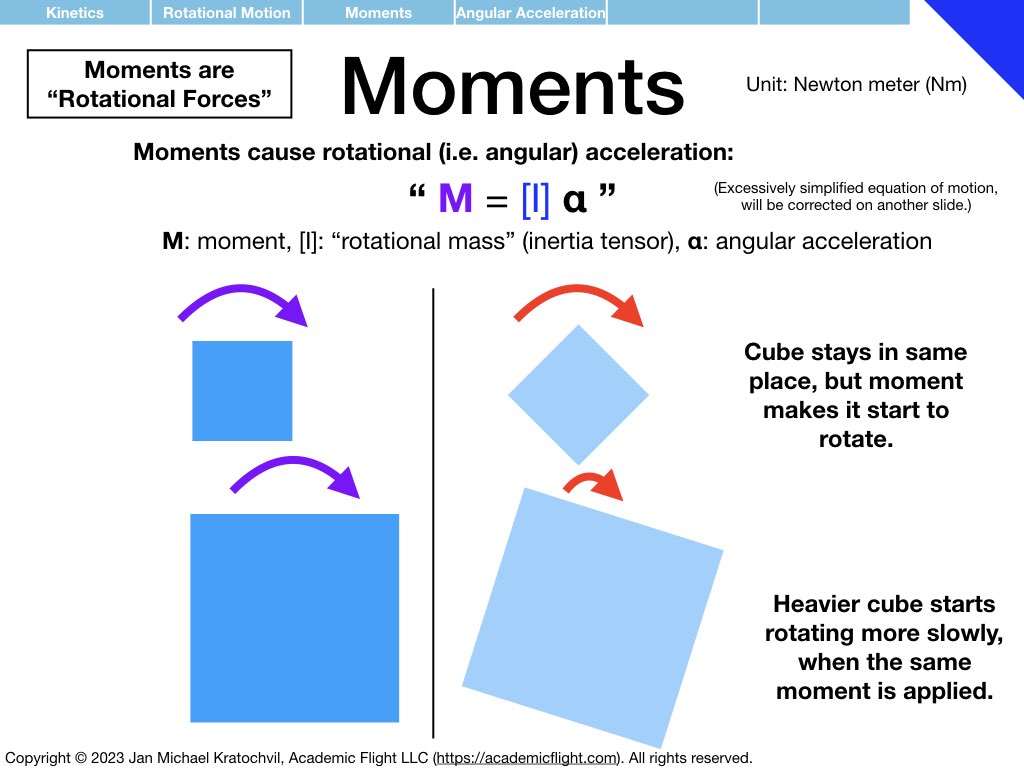
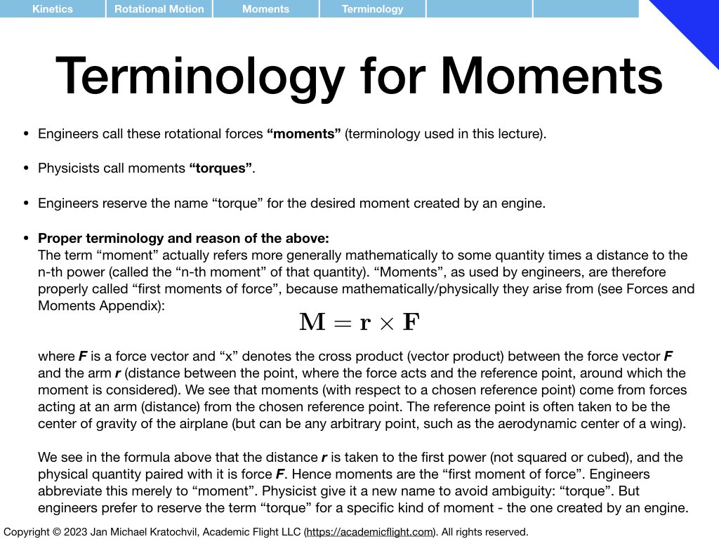
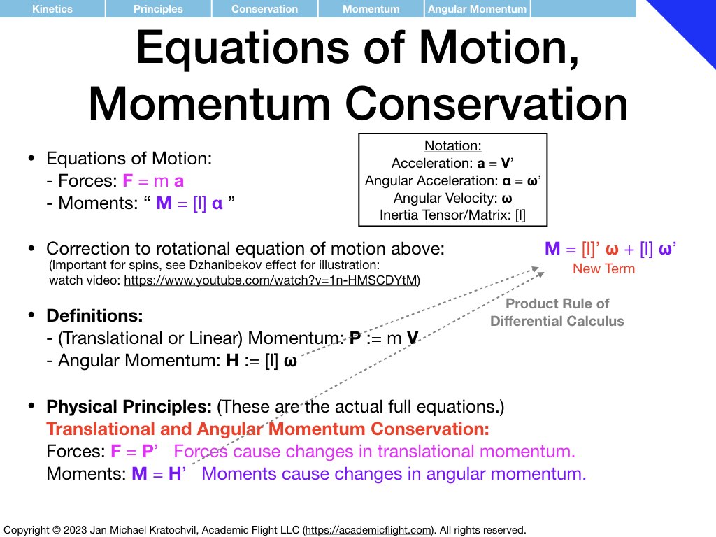
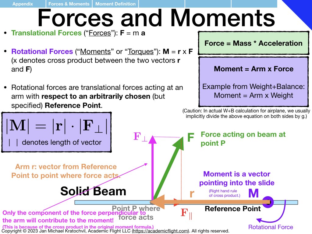
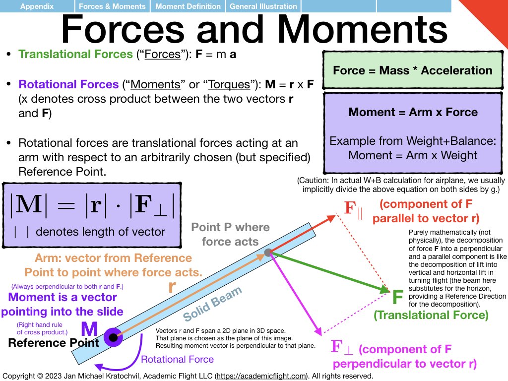
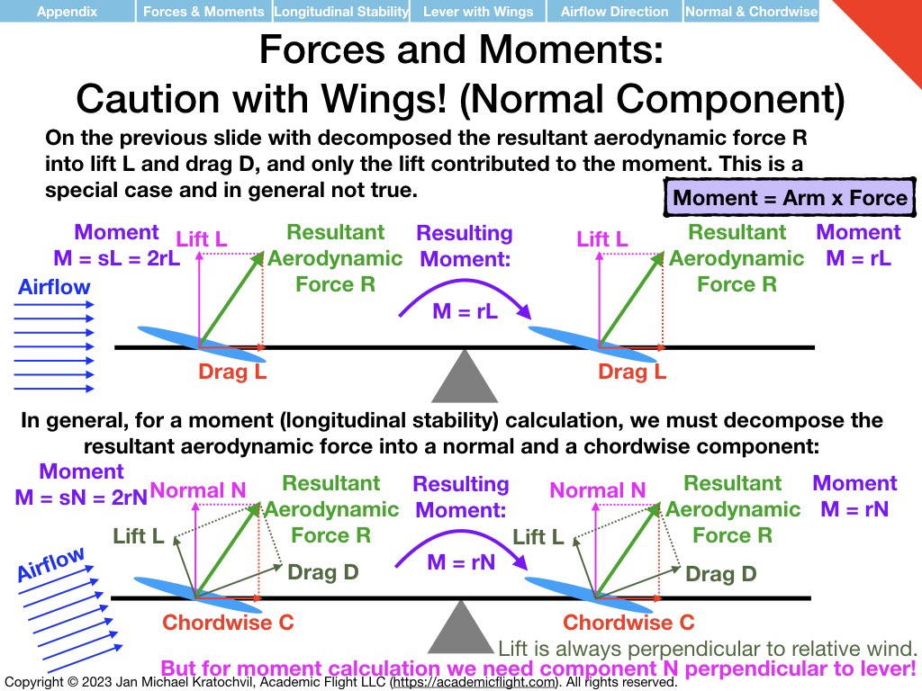
NOTE 1: In the slide set below, moments (“rotational forces”) are introduced as something abstract, as a black box, because for now we want you to think of them independently as a different type of force, one that causes rotational motion rather than translational motion. How moments are actually generated by forces is explained further below in the Forces and Moments Appendix: moments are generated by forces according to equation \(\mathbf{M} = \mathbf{r} \times \mathbf{F}\), where M is the moment generated, r is the arm (direction and distance) at which the force vector F acts, and \(\times\) denotes the vector product, which takes into account only the component of force F that is perpendicular to the arm r. Do not worry about this for now, it will be explained further below.
NOTE 2: Slides dealing with the inertia tensor \([I]\) explicitly and with inertial coupling properly are still missing below and will be added later – either here or when we discuss roll coupling and spins. We will also need to introduce the equation of motion for rotational physics in component form for that.
Video Links
The images of the lecture slides above contain several links to videos on YouTube from other sources, illustrating some of the more perplexing properties of rotational motion not found in translational motion. For convenience, these links are provided in clickable form below.
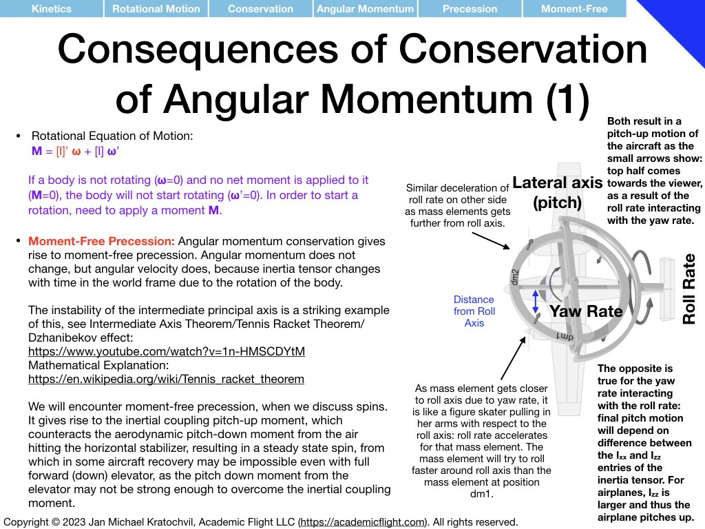
Illustration of moment-free precession:
Intermediate Axis Theorem/Tennis Racquet Theorem/Dzhanibekov Effect:
https://www.youtube.com/watch?v=1n-HMSCDYtM
Mathematical explanation on Wikipedia:
https://en.wikipedia.org/wiki/Tennis_racket_theorem
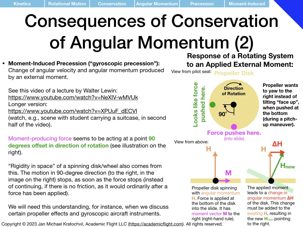
Lecture by Walter Lewin on moment-induced precession:
Short clip:
https://www.youtube.com/watch?v=NeXIV-wMVUk
Longer version:
https://www.youtube.com/watch?v=XPUuF_dECVI
Watch the suitcase scene starting at 41:00 minutes into the last video. If as a pilot you do not understand the gyroscopic precession of your propeller, you will be as surprised in the airplane as this student carrying a suitcase to the airport (and especially in a tailwheel airplane you may be heading for the bushes before even having had the chance to lift off the runway).
Forces and Moments Appendix: Foundations for Weight & Balance and Longitudinal Stability
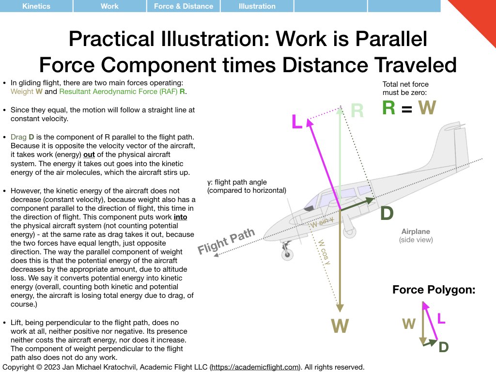
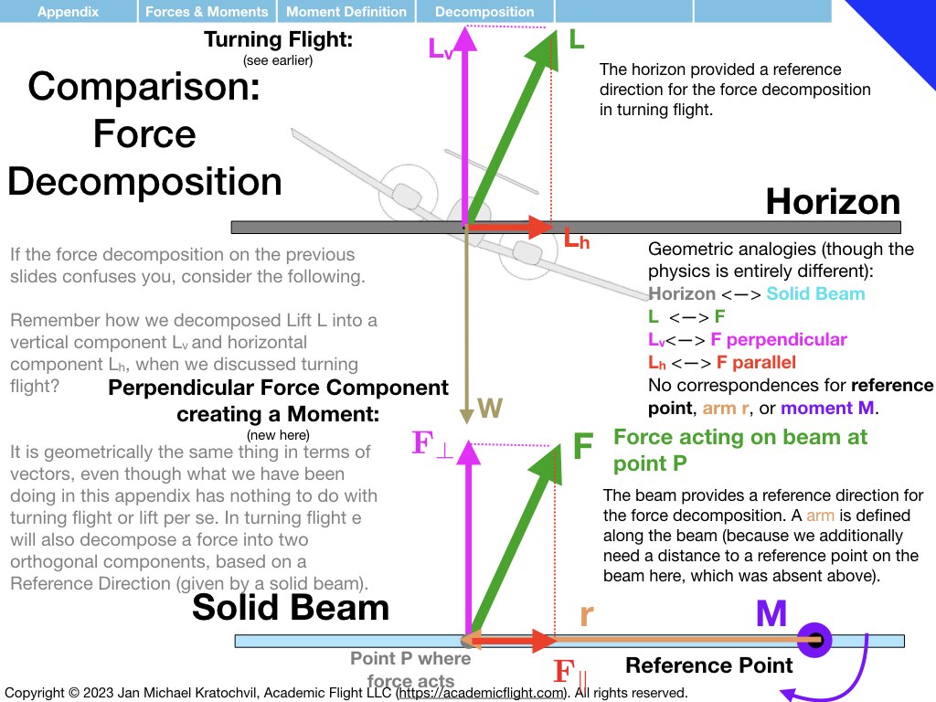
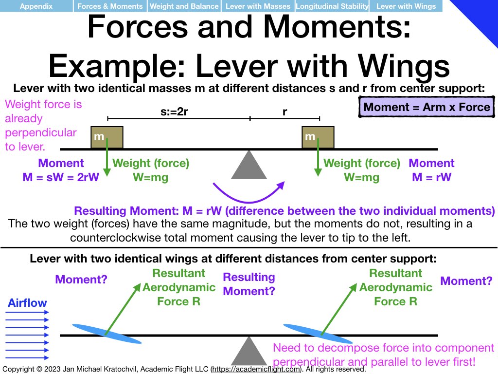
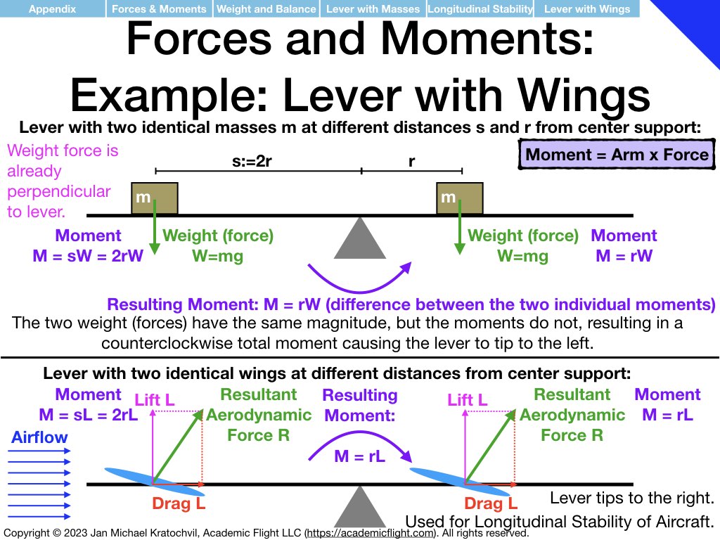
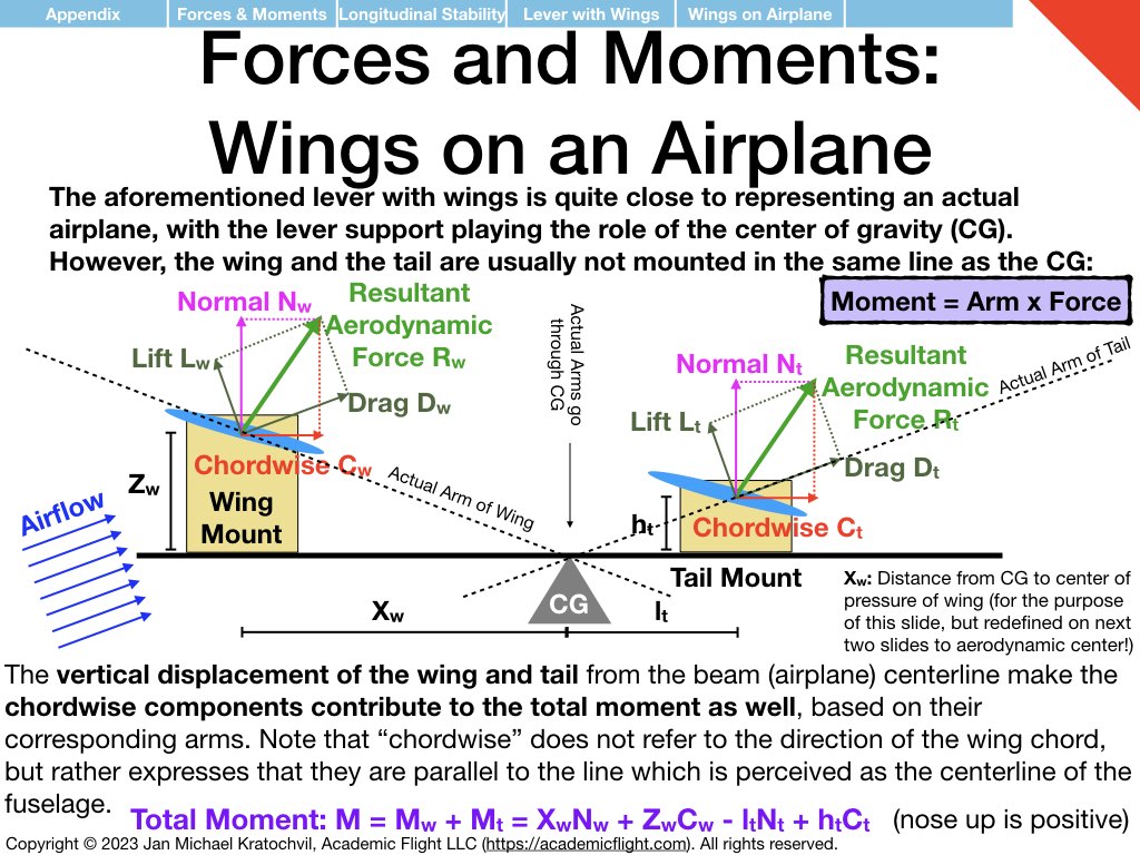
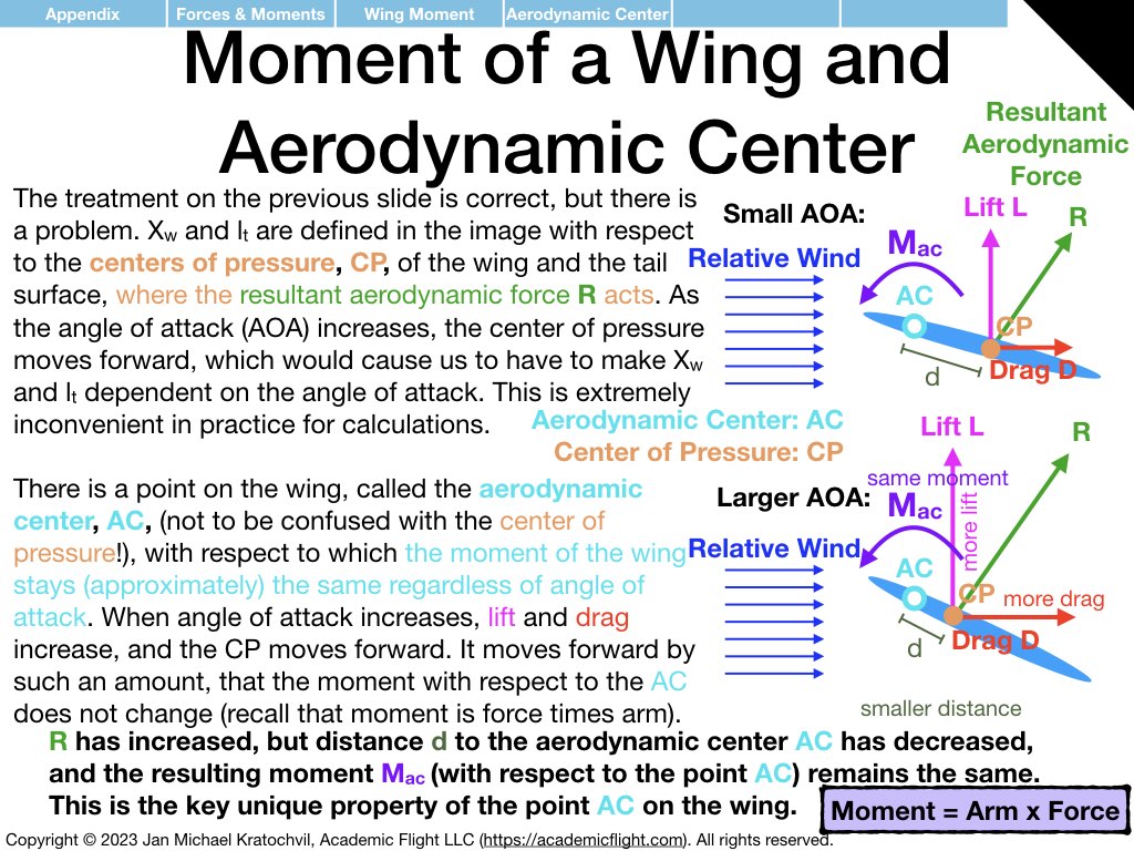
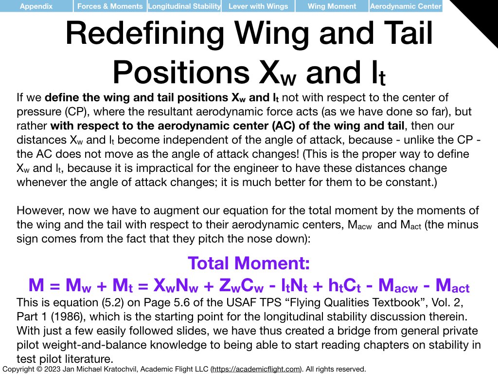
Having understood the similarities and differences between translational physics and rotational physics, and having understood what moments are and that they are “rotational forces”, let us apply these somewhat abstract physics concepts to two particular cases: weight and balance of aircraft and static longitudinal stability.
The examples below just explain how the physics enters the picture. How to do the full weight and balance calculation before a flight in an aircraft will be covered in a separate lecture soon. Static and dynamic longitudinal stability of an aircraft also needs additional discussion. But below we explain the prerequisite knowledge how exactly the physics enters both of these problems.
Please study the above set of slides diligently, because it forms the basis of our discussion of aircraft weight and balance (see PHAK Chapter 10) and of longitudinal stability, which we will encounter in the next lectures.
Connection to Next Lecture (Lecture 5)
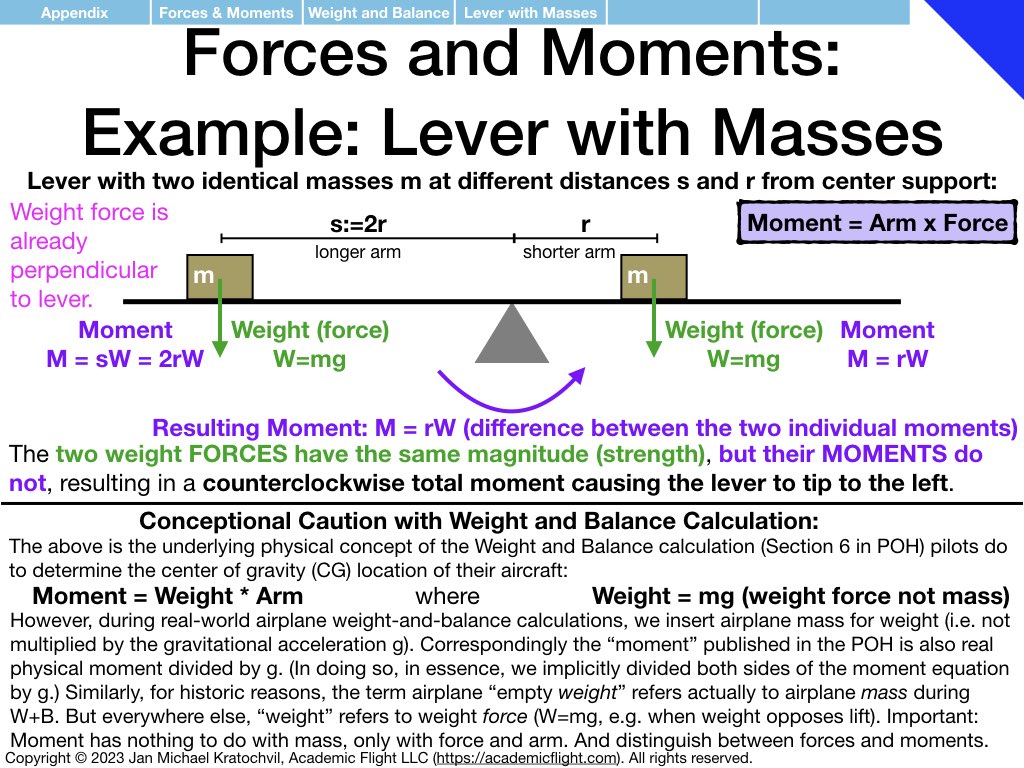
The reader is highly encouraged to read Chapter 10 on Aircraft Weight and Balance in the PHAK before the next lecture (Lecture 5). It builds on the concepts discussed in the Forces and Moments Appendix above. In particular, the lever resting on a fulcrum, having different masses placed to the left and to the right at different distances, is exactly the problem of weight and balance. These masses represent the empty airplane, the pilot(s), passengers, fuel, and any baggage or cargo you may carry; each of these is a block of mass located at some distance measured – say – from the left end of the lever.
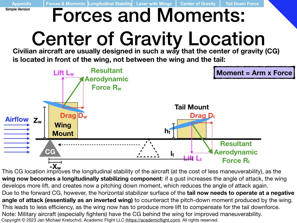
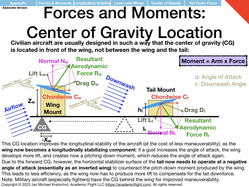
As a pilot, you need to compute the location of the center of gravity of you fully loaded aircraft and see, if it is within the tolerances given by the manufacturer in the aircraft’s Pilot’s Operating Handbook (Section 6 on Weight and Balance). This is incredibly important for safety in flight. This problem is nothing else than determining, where you would have to place the fulcrum to suspend the lever without it tipping to one end or the other, given a bunch of masses at different positions placed on the lever, which represent what you loaded into the airplane.
The Pilot’s Operating Handbook also provides the distances (arms) of the locations, such as pilot seat, passenger seat, baggage compartment, etc. The weights of the objects you need to measure yourself. The weight of fuel is 6 lb per gallon, and the arm (distance from the reference datum, e.g. the front of the airplane) of the fuel tanks is again provided in the POH. Note that your center of gravity may shift during flight, as you consume fuel (you are essentially removing one of the masses from your lever during flight, so you need to do this computation with fuel and without.