Private Pilot Ground School 2023-2024 – Tutorial 3
Introduction
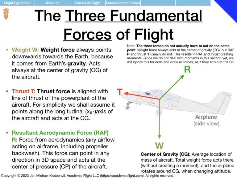
In Tutorial 3 we practice the drawing of the forces of flight: weight W, thrust T, lift L, drag D, and sideforce Y, with the procedure taught in the lecture. Lift, drag, and sideforce are the three spatial components of the resultant aerodynamic force (RAF), and oriented based on the direction of the velocity vector of the aircraft.
Because all the problems below will be left-right symmetric, there will not be any sideforce Y in any of them. Just decompose the RAF into lift L and drag D. Weight W will always be present. Thrust T will only be present in one of the problems (most are power-off situations), but because it will be pointing into the blackboard and will simply be cancelled by drag out of the blackboard, we will not bother drawing it either.
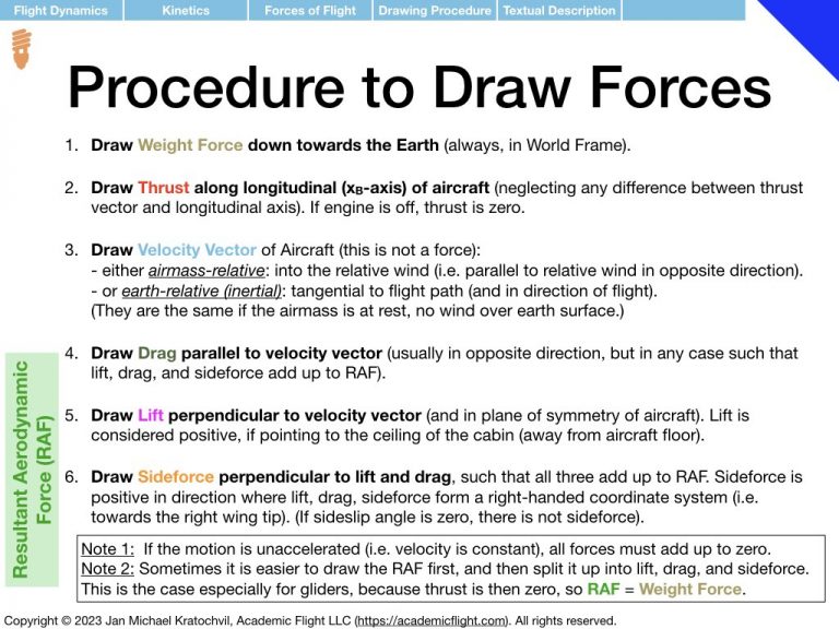
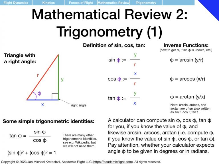
As a reminder, the procedure of drawing the forces of flight is repeated in the slides from the lecture below. A slide with a review of trigonometry is also appended, as you will need it to write down the equations for the forces parallel and perpendicular to the flight path, as a second task after drawing the force diagrams.


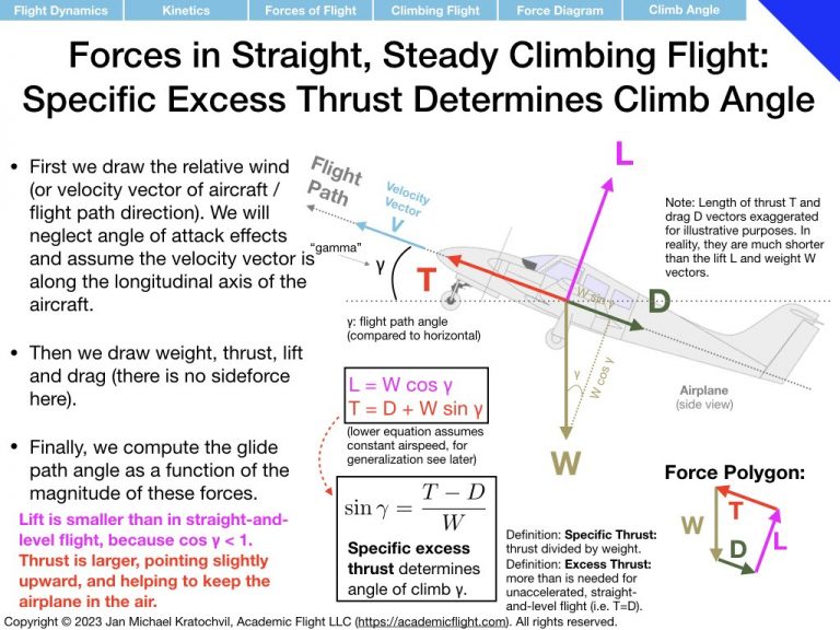
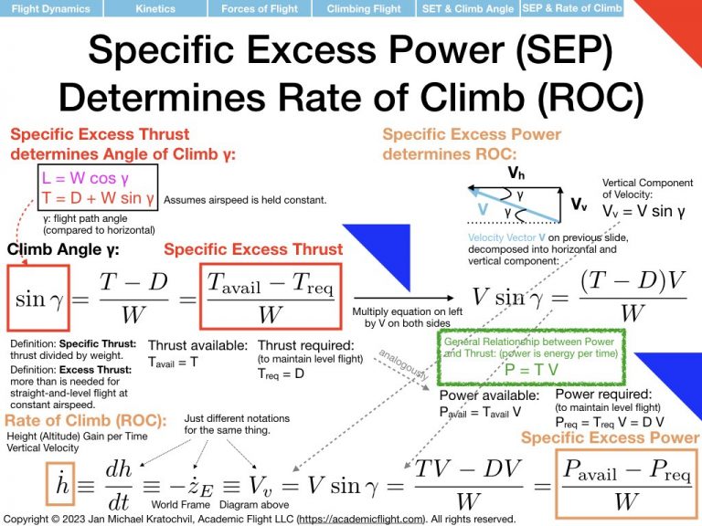
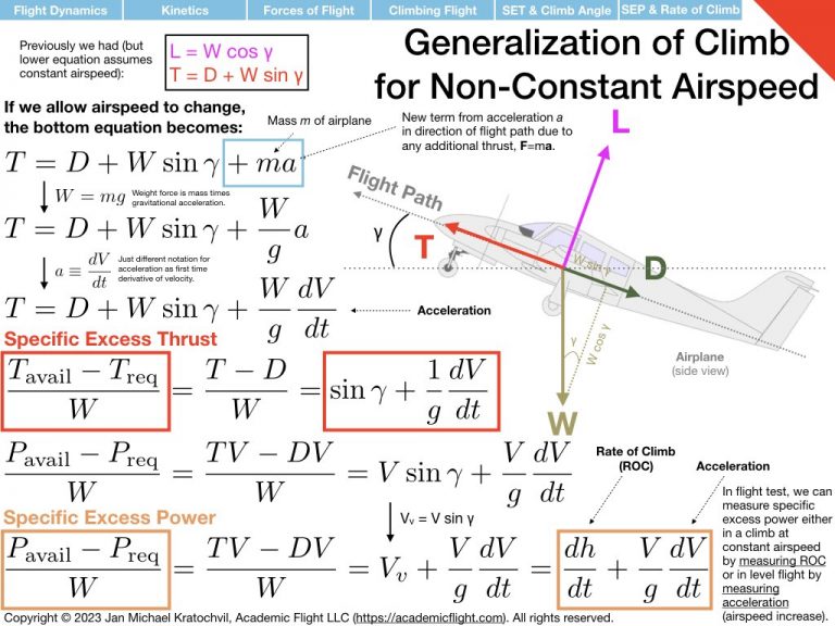

In this tutorial, you will be asked to draw the forces of flight in several situations and then – as a slightly more advanced step, draw conclusions from you drawings. To draw the conclusions, consider the forces not horizontally and vertically, but rather in the direction of the flight path and perpendicular to it. The two examples from the lecture are provided below: straight-and-level flight, climbing flight at constant airspeed.
Due Date: Before Lecture 4
Solutions for this tutorial are part of the presentation of Lecture 4 and will be covered in the next class, so please try to do these problems before the next lecture, so you get to practice thinking about these problems, before seeing the solution. If you are seeing this page after the course happened, try to do this tutorial before you view the presentation slides of the next lecture. Practicing on your own and trying to figure things out yourself, rather than just passively viewing the solution – whether you are able to find the correct solution or not – is a very important part of your thinking skill development and education.
Problem 1: Straight, Power-Off Gliding Flight at Constant Airspeed
Description
In the first problem, consider gliding flight without any thrust coming from the engine. This would be the case in a glider/sailplane, or in a single-engine airplane after an engine failure, and is an important flight regime to understand and practice in flight for any pilot. The air is assumed to be at rest with respect to the earth, so the aircraft is continuously losing altitude at a constant rate, as it is moving forward at constant airspeed in a straight line.
Since there is no thrust and no sideforce in this problem, we are left with only weight W, lift L, and drag D. Lift and drag add up to the resultant aerodynamic force (RAF), of course. Since the RAF is the only other force – other than weight – it has to be equal and opposite to weight, for the motion of the aircraft to be in a straight line at constant velocity. Use this fact to help you with the drawing of lift and drag. The flight path is inclined downwards by flight path angle \(\gamma\) (similarly to how in climbing flight it was angled upwards).
Tasks
- Draw the airplane viewed from the side, the flight path, as well as weight, lift and drag force. Then think about which forces need to equal each other in the direction of flight, and which forces need to equal perpendicular to the flight path.
- Which force(s) help move the aircraft forward along the flight path? Which force(s) try to hold it back?
- Write down the force equations in both of these directions using trigonometry and the flight path angle \(\gamma\), just like we have done for climbing flight in the lecture.
- Finally, draw conclusions about which important relation between which quantities the glide path angle \(\gamma\) depends on. This will be tremendously important for glide distance. And which properties of the airplane does \(\gamma\) not depend on?
- Bonus Task: From the force equations you wrote down above, can you compute the glide speed along the flight path, which with the aircraft is moving? Can you also find an expression for the vertical sink rate in terms of the parameters \(W, C_L\), and \(C_D\)?
Problem 2: Glider Climbing at Constant Airspeed in Rising Air
Description
In this problem we wish to draw the forces of weight, lift and drag for a glider climbing in a straight line at a constant airspeed in an airmass that is rising at a constant velocity. There is no thrust here, since the glider has no powerplant. The glider is gaining altitude and the straight flight path is therefore angled upwards, because the whole airmass, in which the glider is flying, is rising faster than the glider would be sinking in still air in gliding flight.
This is a case, where the air exhibits a relative motion with respect to the earth. The rising air is a form of wind. Therefore, the relative wind does not come from the direction of the flight path anymore. This means that we have two possible definitions for the velocity vector of the aircraft now:
a) An airmass-relative velocity vector, VA, pointing in the direction the aircraft is flying into with respect to the air. This means, this velocity vector is pointing directly into the relative wind and has magnitude equal to the airspeed, which the aircraft (and its airspeed indicator) experience.
b) An earth-relative (or inertial) velocity vector, VE, pointing in the direction of the flight path (tangentially to the flight path). Geometrically, this looks more like the velocity vector we had in previous cases; it indicates the velocity of the aircraft on its flight path with respect to the earth, not caring about the wind direction. The velocity (direction and speed) of this velocity vector is something a GPS would indicate, which keeps track of how the aircraft is moving in 3D space, but knows nothing about any air currents (wind) experienced by the aircraft.
Both velocity vectors above, VA and VE, are valid definitions; we just have to be explicit about which one we use. And we must use the same one for both lift and drag, when we use it to do the force decomposition of the RAF. Therefore, in the problem, we will ask you to do both cases separately. Lift and drag will acquire somewhat different interpretations, depending on which velocity vector definition is used.
Aside from the above complication, this problem is pretty straightforward. There are only two fundamental forces of flight here, just like in the gliding flight example of Problem 1: weight and RAF. Therefore, the RAF must be equal an opposite to weight (because the motion is in a straight line at constant airspeed). And as always, lift L and drag D have to add up to the RAF in the force diagram.
Tasks
- Draw weight W, lift L, and drag D for this situation, using the airmass-relative velocity vector for the lift-drag force decomposition of the RAF. Hint: In order to do this, draw a glider in sideview in climbing flight, but with no thrust. Draw the direction of the relative wind that the glider experiences (this is not straight from the direction of flight, because the airmass is rising). This will determine the direction of the airmass-relative velocity vector of the aircraft. Using this airmass-relative velocity vector, determine the direction with respect to which you do the force decomposition of the RAF into lift and drag, and then draw these forces (such that they add up to the RAF).
- Do the same in a separate drawing, but this time using the earth-relative (inertial) velocity vector of the aircraft for the RAF decomposition into lift and drag. The earth-relative velocity vector indicates the aircraft’s progress along the flight path; therefore, this velocity vector points in the direction of the flight path now, not into the relative wind like in the drawing before.
- Interpret in each of the above two cases, which force(s) pull the aircraft forward along the flight path and help it gain altitude. Which force(s) hold it back? In particular, what does drag do in the earth-relative velocity vector picture?
- Which of the two velocity vector definitions do we need to use, if we want to compute lift and drag from the aerodynamic lift/drag equations and the lift curve/drag polar?
Problem 3: Turning Flight (Level Turn)
Description
In this problem we study turning flight. Specifically, we take a look at an airplane in a level turn, flying at a bank angle \(\mu\) (angle of wings with respect to the horizontal). The airplane in this problem is flying in a circular flight path at constant airspeed and constant altitude.
Because the flight path is curved, not a straight line, this is an accelerated motion. Even though the forward airspeed remains constant (magnitude of the velocity vector), the velocity vector constantly changes direction.
We are not concerned with the directional change of the velocity vector and will simply draw the airplane from behind. However, we do note that, because the motion is now accelerated, the force polygon is not closed anymore: all the forces do not add up to zero. Your task will be again to draw the forces of flight. We shall assume, however, that thrust T opposes drag D (in and out of the blackboard), and will not draw these forces. Thus the only forces remaining for you to draw are weight W and lift L. We will also draw some conclusions.
Tasks
- Draw an airplane from behind, not wings level but rather with wings inclined with respect to the horizon by bank angle \(\mu\). Draw the weight W and lift L force vectors.
- Which component of lift must equal weight, in order for the airplane to be able to hold altitude? What does this tell us about the total length of the lift vector?
- Which component of lift is not compensated for by any other force? What is its function for the aircraft motion along the aircraft’s flight path?
- Using the definition of load factor, \(n:=L/W\) and employing trigonometry, find the expression for load factor as a function of bank angle \(\mu\). Plot your result, and see if you can reproduce Figure 5-53 in Chapter 5 of the FAA Pilot’s Handbook of Aeronautical Knowledge (PHAK) 2023, Page 5-34, which shows load factor as a function of bank angle in a level turn.
- The general accelerated stall speed formula, \(V_{Sacc} = \sqrt{n}\,V_S\), where \(V_S\) denotes straight-and-level stall speed, is always valid. Use the above expression you obtained for load factor and the general accelerated stall speed formula to obtain an expression for accelerated stall speed in a level turn as a function of bank angle. Plot your result (accelerated stall speed vs bank angle) and compare it to the red curve in Figure 5-39 in Chapter 5 of the FAA Pilot’s Handbook of Aeronautical Knowledge (PHAK) 2023, Page 5-26 (the black curve in the plot in the handbook you have already computed in the previous point).
Problem 4: Spin
Description
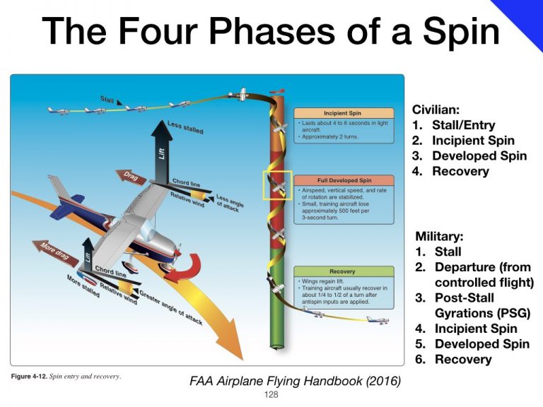
A spin is an autorotational yawing (and rolling) motion with at least one wing stalled, on a flight path almost straight down, see the slide with the image below from the PHAK.
We will consider two cases:
- A Prototype Spin, where the motion is really straight down and the airplane is simply constantly changing heading. In this simple, idealized case, the flight path is straight down exactly along the vertical spin axis.
- A more Realistic Spin, where the motion is on a tight helical flight path around the spin axis, such as depicted in the image above. The spin axis is the vertical axis in the center of the helix (centerline of the colored column in the image above), which the flight path describes around it.
In both cases we will assume that the engine is off (no thrust) and that the motion along the flight path is happening at a constant speed (no acceleration).
Tasks
- Draw the weight W, lift L, and drag D force vectors for the Prototype Spin described above. Do you really need all three, or can you get away with just two (the third one being zero in this simplified picture)?
- Draw the weight W, lift L, and drag D force vectors for the Realistic Spin. What role does the third force play, which you may have not needed above?
When we discuss this briefly in Lecture 4, and on that occasion will also give an outlook on what the moments (rotational forces) do in a spin, since they are actually the more interesting part, which sustains the autorotation. But we have not discussed rotational physics yet. We will take a deeper look at spins in this online private pilot ground school in the Spring Semester 2024, when we will discuss accelerated spins, flat spins, etc., as well as recovery techniques for different kinds of aircraft (wing-loaded vs fuselage-loaded).