Private Pilot Ground School 2023-2024 – Tutorial 3 Solution
Introduction
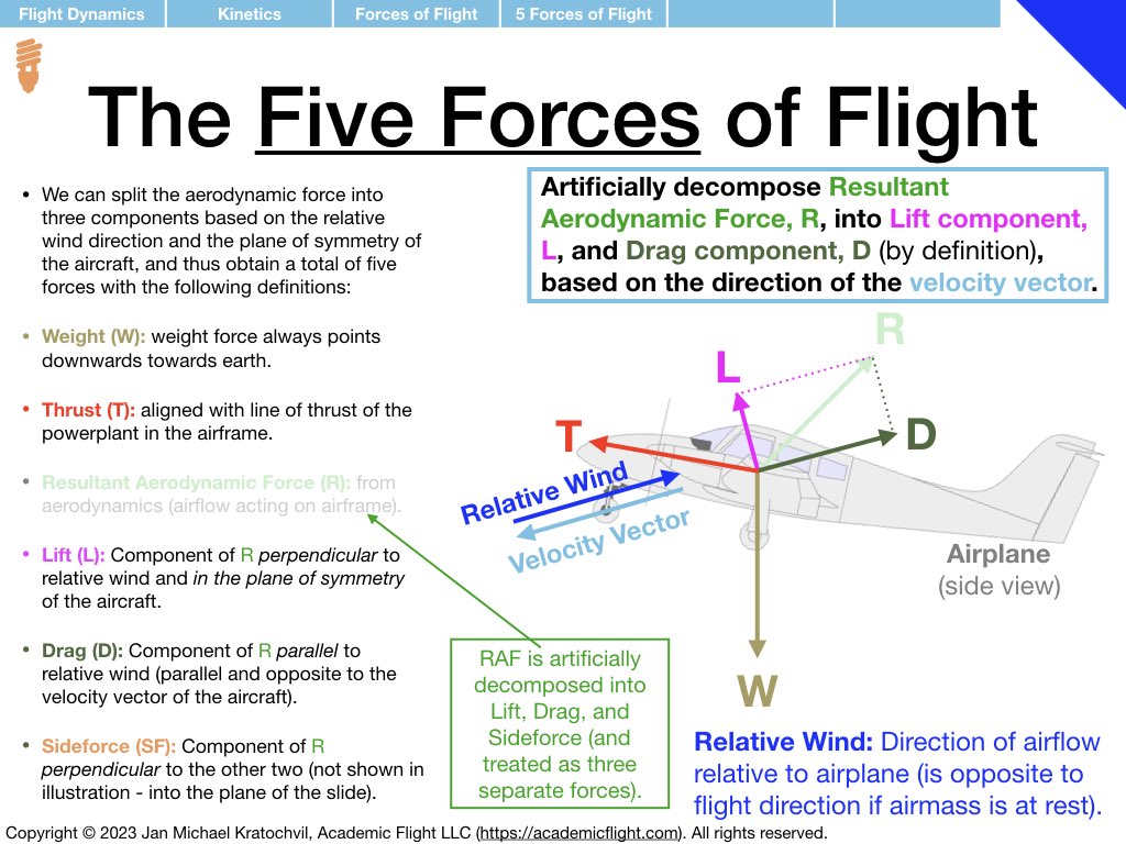
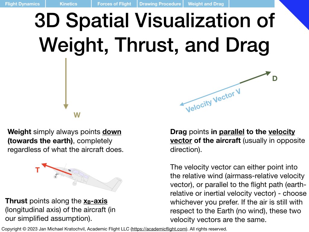
In Tutorial 3 we practice the drawing of the forces of flight: weight W, thrust T, lift L, drag D, and sideforce Y, with the procedure taught in the lecture. Lift, drag, and sideforce are the three spatial components of the resultant aerodynamic force (RAF), and oriented based on the direction of the velocity vector of the aircraft.
Because all the problems below will be left-right symmetric, there will not be any sideforce Y in any of them. Just decompose the RAF into lift L and drag D. Weight W will always be present. Thrust T will only be present in one of the problems (most are power-off situations), but because it will be pointing into the blackboard and will simply be cancelled by drag out of the blackboard, we will not bother drawing it either.
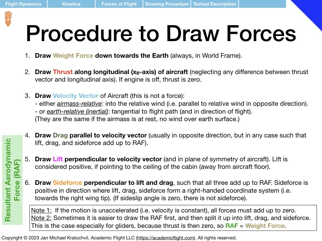
As a reminder, the procedure of drawing the forces of flight is repeated in the slides from the lecture below. A slide with a review of trigonometry is also appended, as you will need it to write down the equations for the forces parallel and perpendicular to the flight path, as a second task after drawing the force diagrams.
Problem 1: Power-Off Gliding Flight
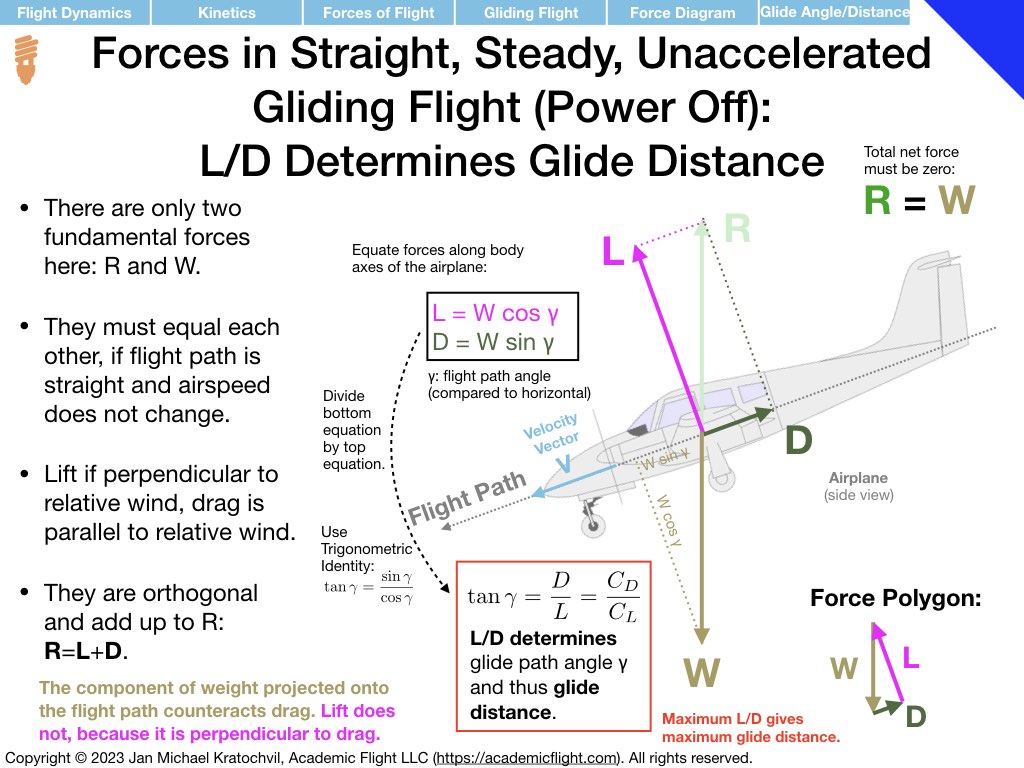
In power-off gliding flight, in a straight line at constant airspeed, all forces must add up to zero. Since there in no powerplant in the aircraft (of it is turned off), there is no thrust. Therefore, we are left with only two fundamental forces: weight W and resultant aerodynamic force (RAF) R. Thus, RAF has to point in opposite direction than weight and have equal magnitude.
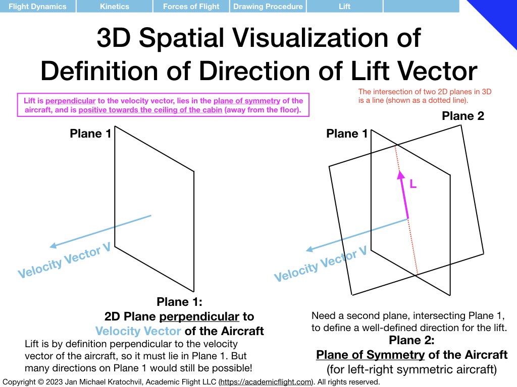
Weight always points down, so RAF has to point up. What we need to figure out is how to draw lift L and drag D, which have to add up to the RAF. For this, we first draw the velocity vector of the aircraft. Then we make drag point parallel to it and lift perpendicular, while also keeping lift in the plane of symmetry of the aircraft (the latter is easy here, since the slide represents the plane of symmetry, if we view the aircraft directly from the side.
The first slide of the set of three slides below answers all the main questions of the problem, except for the bonus tasks. Lift and drag are drawn. Drag points parallel to the velocity vector, and therefore backwards. It is a retarding force that costs the aircraft energy by virtue of the aircraft moving against it. Since lift is perpendicular to the velocity vector and the direction of flight, it does not contribute to the forward motion of the aircraft at all and it also does not help to counteract drag. The force counteracting drag is the weight force, which now has a non-zero component along the flight path forward.
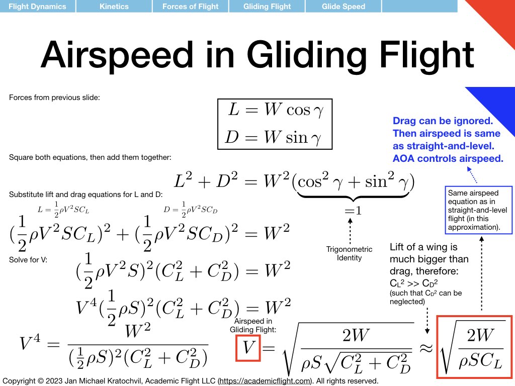
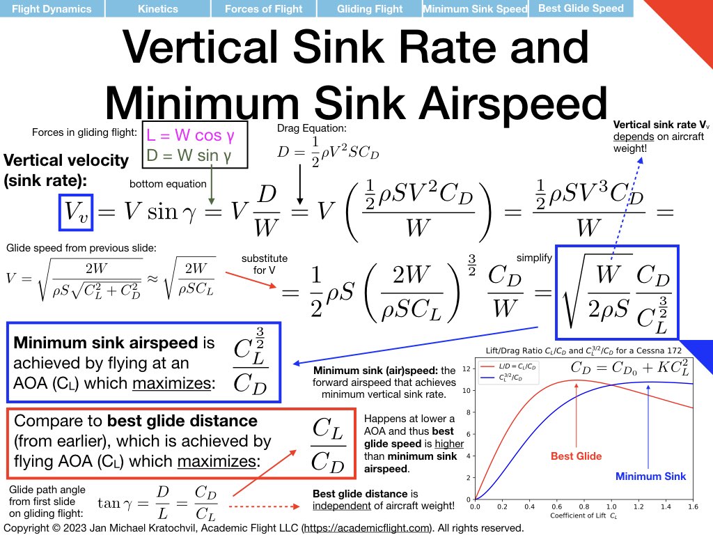
The first slide also writes down the force equations parallel and perpendicular to the force vector, using basic trigonometry, and proceeds to compute the equation for glide path angle, which will give you glide distance. Explanations are provided in the slide directly. We see that glide path angle \(\gamma\) only depends on \(C_L\) and \(C_D\), so both lift and drag coefficients play an important role. Since both depend on angle of attack \(\alpha\), angle of attack determines glide speed. Note that weight W and air density \(\rho\) are nowhere to be found (cancelled out), so the glide path angle (and this glide distance) are independent of aircraft weight. There is one specific angle of attack giving maximum glide distance – regardless of aircraft weight. The associated best glide speed, however, does depend on weight (Slide 2).
Slides 2 and 3 below tackle the bonus tasks: they compute the glide speed of the aircraft and the sink rate, respectively, from the same two force equations, by just combining them differently mathematically.
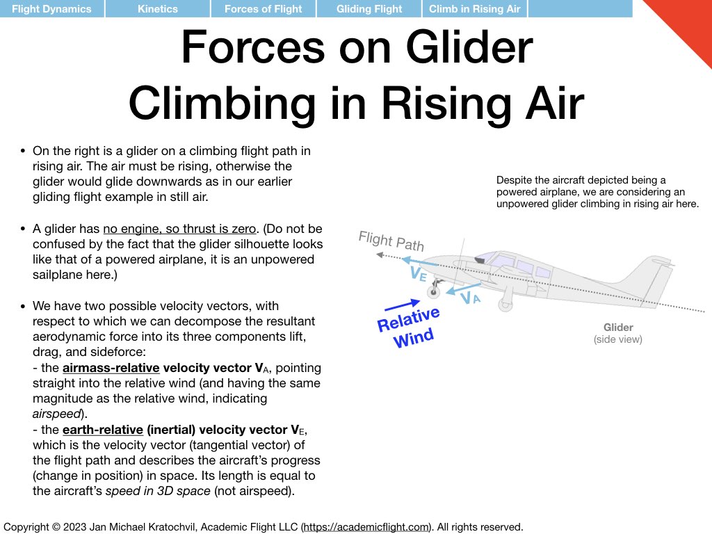
Problem 2: Glider Climbing in Rising Air (without Engine Power)
This problem is similar to the powered climbing flight problem discussed in Lecture 3, but without the thrust vector. The forces still need to add up to zero, because the motion is happening in a straight line at constant speed. We just have to find a way to arrange the vectors differently.
This problem also bears some similarity to Problem 1, in that there are only two fundamental forces at work here: weight and resultant aerodynamic force (RAF). Therefore, we have again RAF just opposing weight like in Problem 1. The challenge is to draw the lift and drag vectors properly.
Since their directions are based on the direction of the velocity vector, we must draw the velocity vector first. We have two valid choices. We can draw the velocity vector into the wind, giving us velocity with respect to the airmass (the airspeed indicator would give us the magnitude of this velocity, and we could use a weathervane to determine its direction. Or we can use the earth-relative velocity vector, which simply give our velocity in 3D space along the flight path; this is the velocity the GPS would indicate, which knows nothing about airflows.
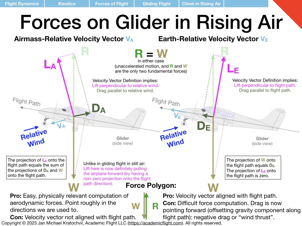
.The slides below illustrate the two solutions and the different interpretations that lift and drag get. If we draw them with respect to the airmass-relative velocity vector, lift now is angled forward with respect to the flight path and counteracts the components of drag and weight backwards along the flight path (this is unlike in gliding flight in still air, where lift ended up being perpendicular to the flight path and didn’t pull “forward” at all).
If on the other hand, we choose the earth-relative velocity vector, lift will point again perpendicularly to the flight path and therefore does nothing to propel the aircraft forward, and it is now up to drag to counteract the rearward component of gravity. In order for drag to be able to do this, it must point forward! This is not as surprising after some thought. Yes, drag is typically an aerodynamic resistive force, but in this example, it is aerodynamics that helps us climb, so the rising airmass is actually blowing us upwards (and letting us gain potential energy), rather than slowing us down and costing us kinetic energy (or potential energy if we insist on maintaining airspeed).
Both definitions of lift and drag forces are valid, we just have to be explicit about which one we mean. However, if we want to use our aerodynamic equations for lift and drag (lift and drag equations, lift curve, and drag polar), we must use the airmass-relative velocity vector.
The lift and drag forces based on the earth-relative velocity vector can be useful for us to study the motion of the aircraft through space, by they know nothing about aerodynamics, and we can thus not use the aerodynamic equations to compute them. If we did want to compute them, we could use the lift and drag equations for the airmass-relative definitions for lift and drag and then afterwards perform a coordinate system rotation from the so called wind frame to the so called velocity frame.
Problem 3: Turning Flight (Level Turn)
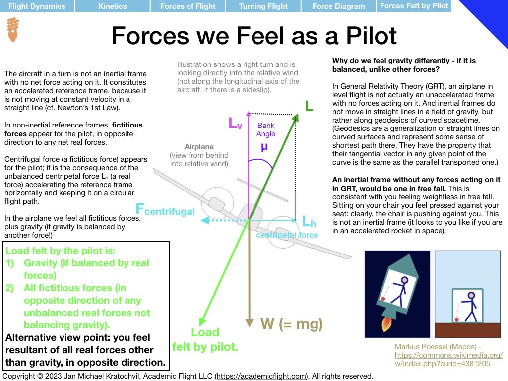
Turning flight is not a motion in a straight line. Therefore, even though we will keep airspeed constant, this is an accelerated motion. A continuous, unbalanced, net centripetal force is needed pointing to the inside of the circular flight path, to keep the aircraft on the flight path – just like satellites circle the Earth on their orbits, because the force of gravity continuously pulls them towards the Earth, providing the centripetal force needed (in a Newtonian picture of gravity).
.The most efficient way to create forces perpendicular to the flight path is to use lift. (Drag does not work, because it is by definition parallel to the flight path in a still airmass, and while sideforce would work, this is not efficient – you would be using sideforce, you tried to turn the airplane using rudder and keeping the wings level.)
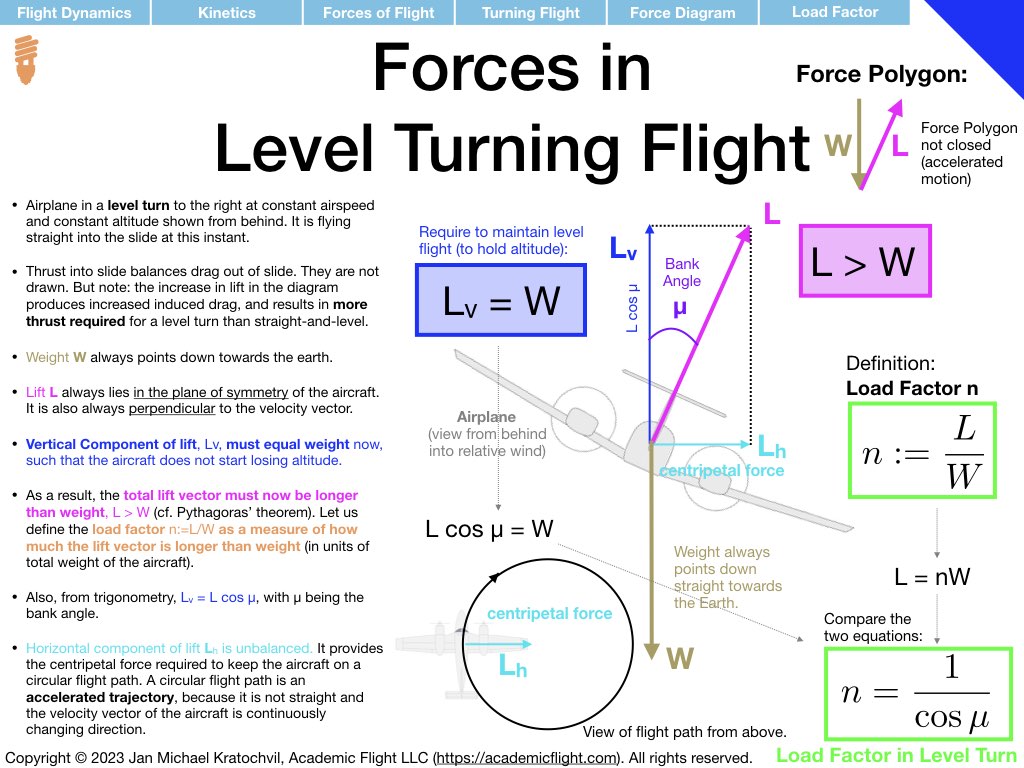
Therefore, we need to get lift to point horizontally into a turn. We do so by establishing a bank angle. Since lift lies always in the plane of symmetry of the aircraft, it then develops a horizontal component, which acts as the centripetal force to keep the aircraft flying in a circle.
The first slide below shows the forces on an airplane, viewed from behind. It is flying straight into the slide. Drag therefore points straight out of the slide, and it is counteracted by thrust into the slide. We assume we have enough thrust to equal drag and maintain airspeed, so we do not actually draw these two forces below. Lift has to be perpendicular to the velocity vector of the aircraft and thus must lie somewhere (anywhere) in the plane of the slide (from this requirement). There is, however, a second requirement: lift must also lie in the plane of symmetry, and so it end up pointing exactly as shown in the first slide below. The horizontal component of lift is also drawn.
If we kept the lift vector the same length as in level flight though, \(L=W\), then the vertical component of lift, which opposes weight, would be too short to cancel weight entirely. This would lead to the weight force accelerating the aircraft downwards: we would start losing altitude.
But we want to hold altitude, so we must make the vertical component of lift longer, so long that it equals weight, \(L_v = W\). The way to do that is to make the total lift vector, \(\mathbf{L}\) longer. This means, we need to create more lift. Remembering the lift equation, we could increase lift by increasing airspeed, but we want to keep airspeed the same. The other option to increase lift is by increasing the coefficient of lift, which – remembering the lift curve – we can do by increasing the angle of attack. Now we are all set as far as the forces are concerned in the plane of the slide.
However, when we increased the angle of attack, we have also increased induced drag. Therefore, we also need to add more power to the engine to create more thrust, which will counteract this drag increase and keep airspeed the same. In summary, the logical progression is:
- Establish bank angle to create a horizontal component of lift to curve your flight path in a turn.
- Increase angle of attack (by pulling back on the longitudinal inceptor (i.e. elevator control)) to increase total lift, such that the vertical component of lift equals weight.
- Add a little bit of power to compensate for the additional induced drag we have created, when we increased total lift.
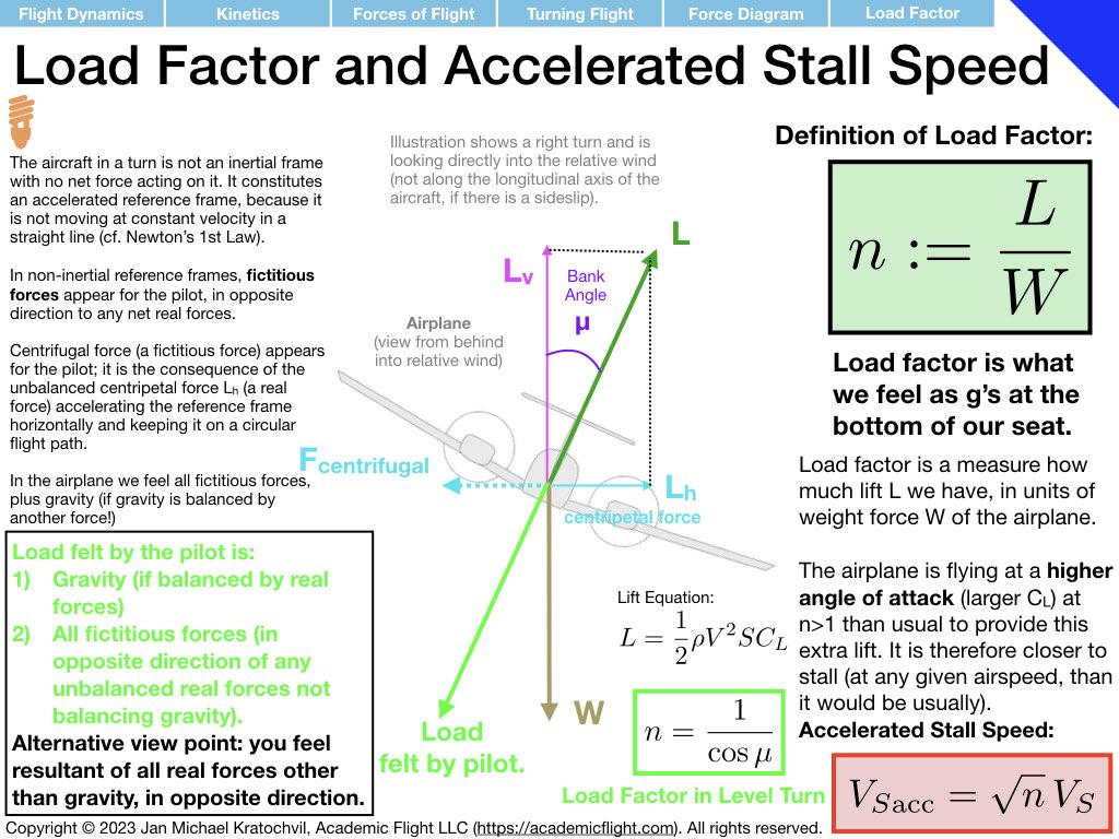
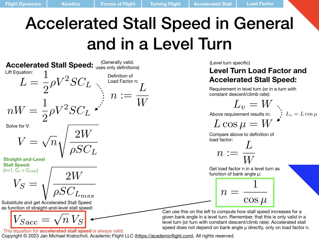
Our next task in the problem was to compute the relationship between bank angle and load factor in a level turn. To this end, we first remind ourselves of the definition of load factor \(n:=L/W\), i.e. load factor measures the amount of lift in units of aircraft weight (or acceleration in units of G (multiples of Earth’s gravitational acceleration). This definition we can easily rewrite as \(L = nW\). From trigonometry in the force diagram, we also quickly find that \(W=L_v=L\cos\mu\), where \(\mu\) is the bank angle. Comparing the two equations yields readily \(n=\frac{1}{\cos\mu\), which is the desired expression. We can now plot \(n\) as a function of \(mu\) and reproduce the corresponding plot in the PHAK. Remember that this relation only holds for a level turn (or a turn with constant climb or descent rate). In general, there is no natural relationship between load factor an bank angle (you can fly in a 90-degree bank angle at \(n=1\) if you like – you just cannot hold altitude.
The final question was to find the accelerated stall speed in a level turn. We recall that the following formula is valid for any maneuver: \(V_{Sacc} = \sqrt{n}\,V_S\), where \(V_S\) denotes straight-and-level stall speed. In particular, bank angle in an of its own does not increase stall speed. If, however, we require that we fly a level turn, then the bank angle comes associated with a corresponding load factor, as just calculated. And as a reasult of that load factor increase, our stall speed in a turn increases as well. Simply inserting the \(n(\mu\)\) relation calculated earlier into the accelerated stall speed formula leads – for a level turn specifically: \(V_{Sacc} = \sqrt{\frac{1}{\cos\mu}}\,V_S\). The slides below illustrate and compute all of this explicitly.
Problem 4: Spin
Description
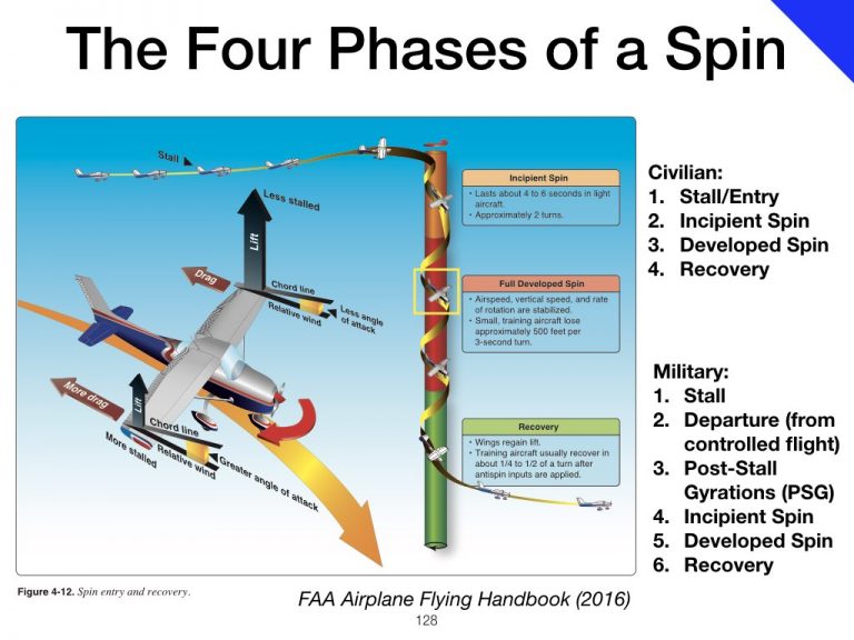
A spin is an autorotational yawing (and rolling) motion with at least one wing stalled, on a flight path almost straight down, see the slide with the image below from the PHAK.
We will consider two cases:
- A Prototype Spin, where the motion is really straight down and the airplane is simply constantly changing heading. In this simple, idealized case, the flight path is straight down exactly along the vertical spin axis.
- A more Realistic Spin, where the motion is on a tight helical flight path around the spin axis, such as depicted in the image above. The spin axis is the vertical axis in the center of the helix (centerline of the colored column in the image above), which the flight path describes around it.
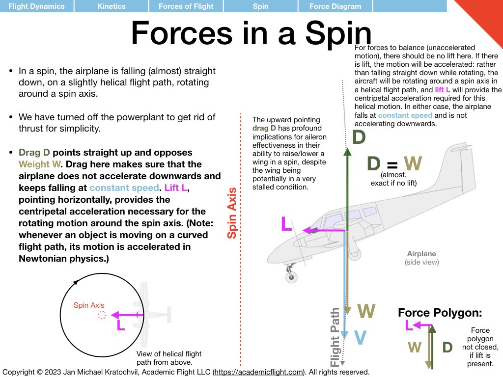
In both cases we will assume that the engine is off (no thrust) and that the motion along the flight path is happening at a constant speed (no acceleration).
Let us look at the straight-down prototype spin first. Since the velocity vector is straight down, drag is straight up and can counteract the weight force all by itself. Lift is not needed. This is drawn in the slide below (if you just ignore the lift vector).
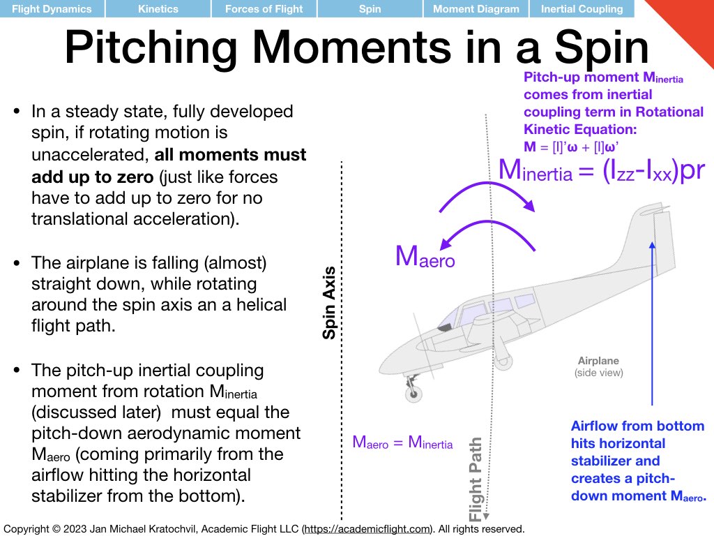
In a more realistic spin, the wing will still produce a bit of lift, despite the high angle of attack. The aircraft motion now becomes helical (see also the above image from the PHAK for an illustration) and lift provides the centripetal force required to keep the aircraft rotating on a helical flight path around the spin axis in the center. (In the previous case, the prototype spin without any lift, the aircraft was descending straight down on the spin axis.)
The fact that drag is pointing straight up has profound implications on aileron effectiveness in a developed spin. Even though the wing may be very stalled and the ailerons not able to create much lift at all, the ailerons can still produce a lot of drag, and is this drag that raises the wing of the downward deflected aileron, such that the ailerons work in a spin as normal. (This is in stark contrast to the stall/spin entry at the beginning of the maneuver, where the ailerons can be completely ineffective for roll control, and may in fact precipitate the departure from controlled flight and exacerbate the spin entry.)